Programming IDEC SmartRelay
IDEC SmartRelay Manual 63
3.3 From circuit diagram to IDEC SmartRelay
program
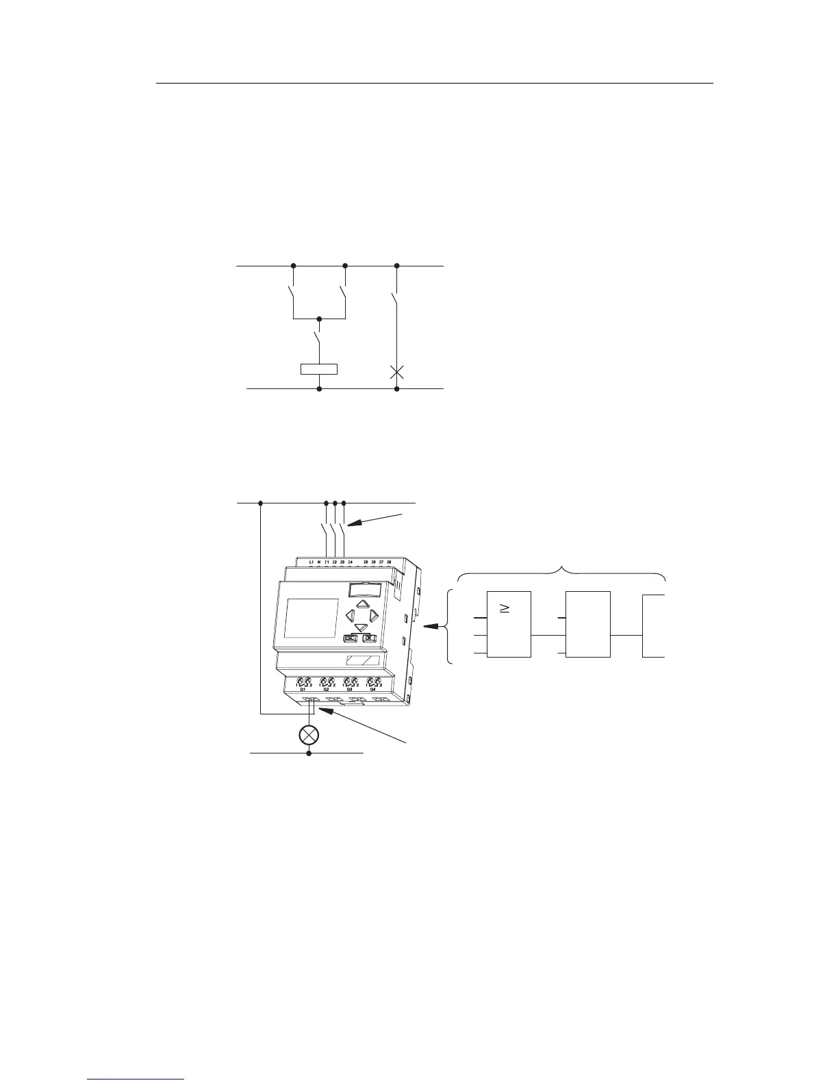
View of a circuit diagram
You know, of course, how a circuit logic is represented in a
circuit diagram. Nevertheless, here is an example:
Load E1 is switched on and off by
means of the switches (S1 OR S2)
AND S3.
Relay K1 picks up when condition
(S1 OR S2) AND S3 is met.
Creating this circuit with IDEC SmartRelay
In IDEC SmartRelay you create a circuit logic by
interconnecting blo
cks and connectors:
S1 ... S3
I3
x
Q1
&
1
I1
I2
x
L1
N
Wiring of the inputs
Circuit program in IDEC SmartRelay
Wiring of the outputs
Phone: 800.894.0412 - Fax: 888.723.4773 - Web: www.clrwtr.com - Email: info@clrwtr.com