IDEC SmartRelay functions
190 IDEC SmartRelay Manual
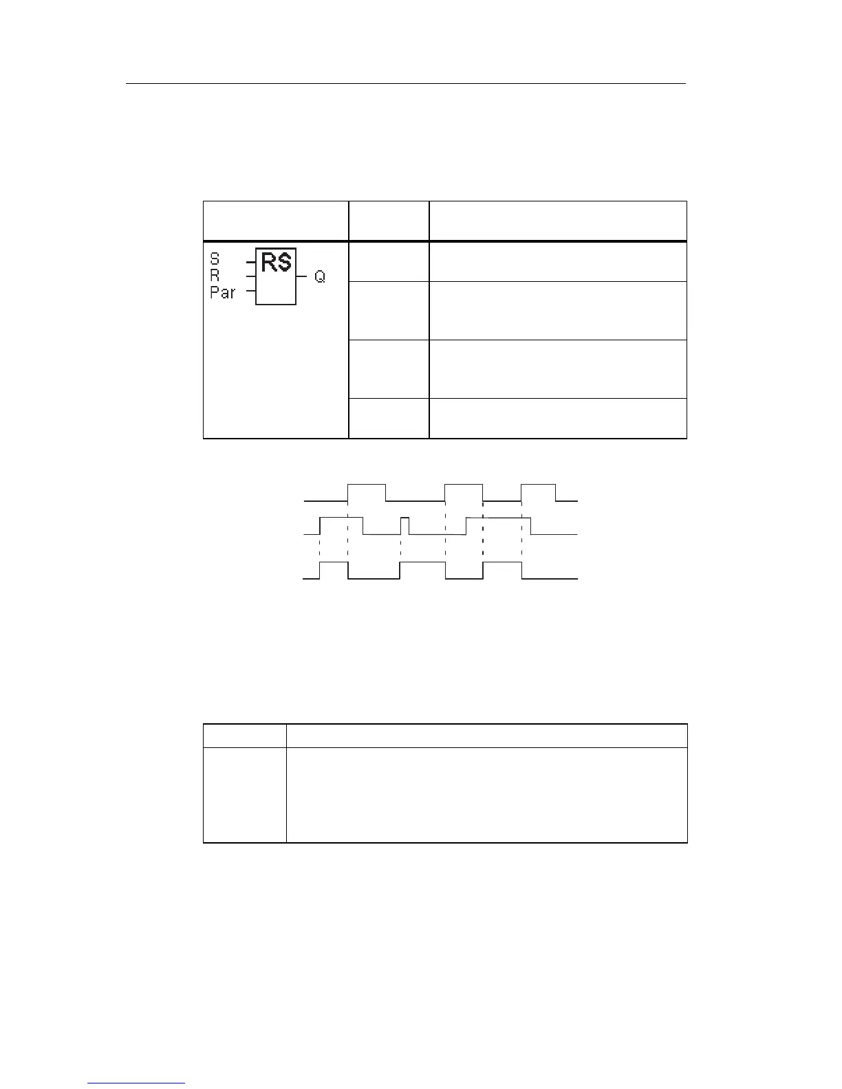
4.4.21 Latching relay
Short description
Input S sets output Q, input
R resets output Q again.
S
R
Q
Timing diagram
Switching response
A latching relay represents a simple binary element. The
o
utput
value depends on the status at the inputs and on the
previous output status. The following table shows the logic
once again:
When retentivity is enabled, the current status of the output
sign
al is re
tained after a power failure.
Symbol in IDEC
SmartRelay
Wiring Description
Input S You set output Q with a signal at input
S.
Input R You reset output Q with a signal at
input R. If S and R = 1, the output is
reset.
Parameter Retentivity:
/ = No retentivity
R = The status is retentive.
Output Q Q is set with a signal at input S, and
reset with a signal at input R.
S
n
R
n
Q Comment
0 0 x The status is retentive
0 1 0 Reset
10 1Set
1 1 0 Reset (takes priority over Set)
 Loading...
