Programming IDEC SmartRelay
58 IDEC SmartRelay Manual
3.1 Connectors
IDEC SmartRelay is equipped with inputs and outputs
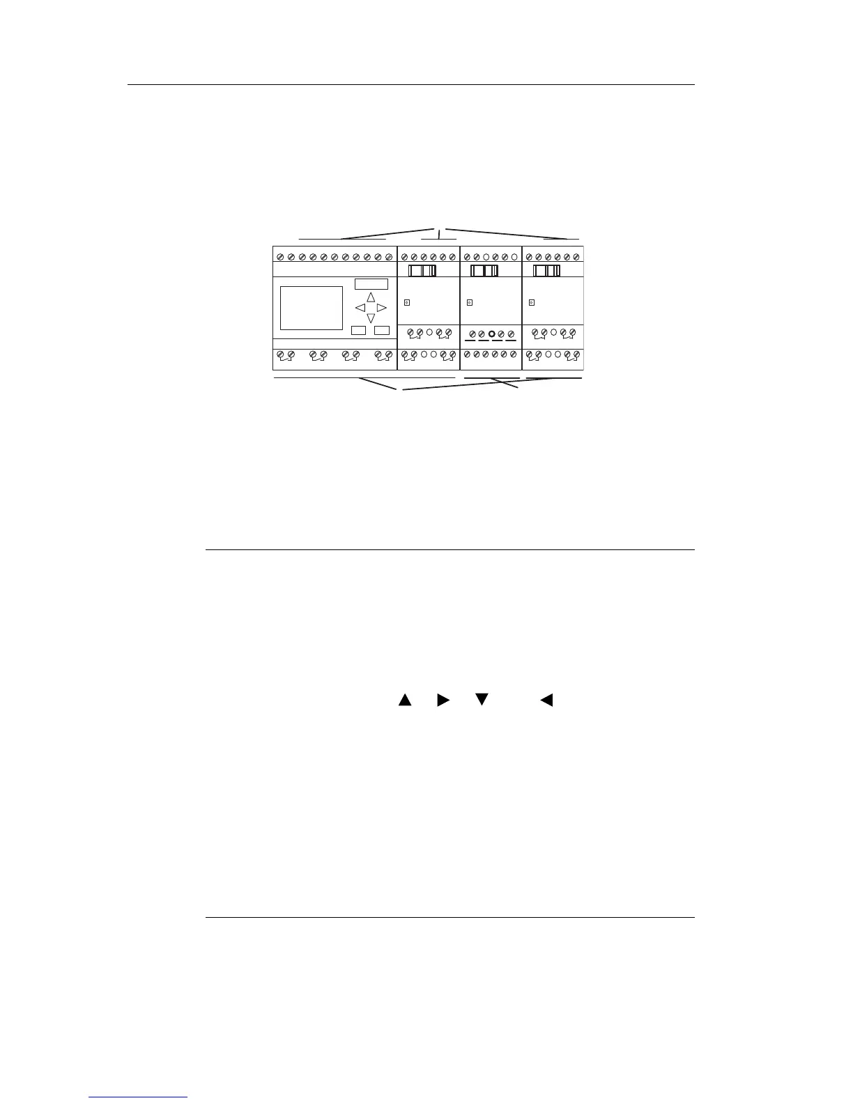
Example of a configuration with several modules:
Each input is identified by the letter I plus a number. When
you look at IDEC SmartRelay from the front, you can see the
input terminals at the top. Only analog modules FL1B-J2B2
have the inputs at the bottom.
Each output is identified by the letter Q plus a number
(FL1
D-K2B2, FL1D-K2BM2: AQ plus number). In the figure,
you can see the output terminals at the bottom.
Note
IDEC SmartRelay can recognize, read and switch the I/O of all
expansion modules regardless of their type. The I/Os are presented
in the installation order of the modules.
The following I/Os and marker blocks are available for creating your
circuit program: : I1 to I24, AI1 to AI8, Q1 to Q16, AQ1 and AQ2,
M1 to M27 and AM1 to AM6. Also available are the shift register bits
S1 to S8, 4 cursor keys: C , C , C and C , four function keys
on the Text Display: F1, F2, F3, and F4 as well as 16 blank outputs
X1 to X16. See Chapter 4.1 for more details.
The following applies to inputs I1, I2, I7 and I8 of FL1E-H12RCE/
FL1E-B12RCE and FL1E-H12SND versions: If you use I1, I2, I7 or
I8 in the circuit program, this input signal is digital. If you use AI3,
AI4, AI1, or AI2, the input signal is analog. The numbering of the
analog inputs is significant: AI1 and AI2 corresponded to I7 and I8
on the FL1D module. With the addition of two new analog inputs for
the FL1E series, these modules optionally use I1 for AI3 and I2 for
AI4. See the graphical representation at 2.1.1. Also note that you
can also use I3, I4, I5, and I6 as fast digital inputs.
The illustration above with numbered AI inputs shows the
conceptual usage of the inputs, not the actual physical
markings on the module.