IDEC SmartRelay installation and wiring
20 IDEC SmartRelay Manual
2.1 Modular IDEC SmartRelay setup
2.1.1 Maximum setup
As defined in Chapter 1, IDEC SmartRelay supports a
maximum of 24 digital inputs, 8 analog inputs, 16 digital
outputs, and 2 analog outputs. You can achieve the
maximum setup in different ways as shown below:
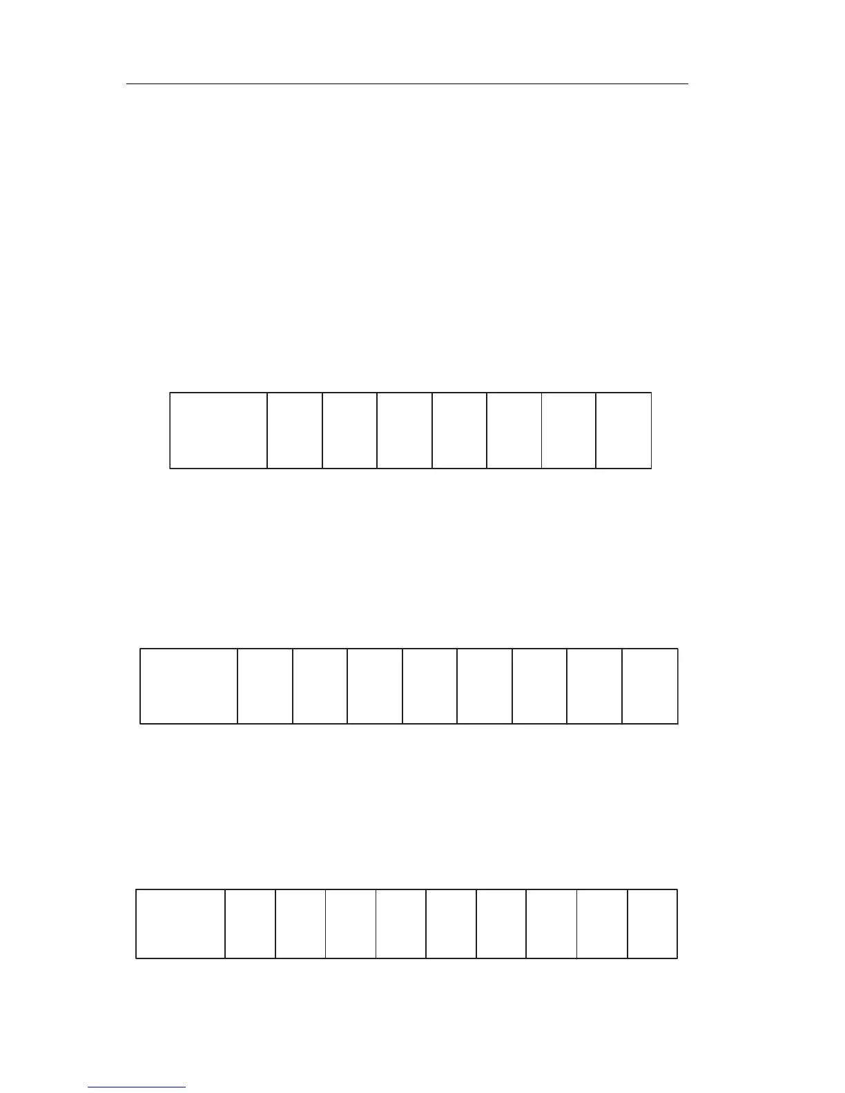
Maximum setup of an IDEC SmartRelay with analog inputs - four
in use
(FL1E-H12RCE/FL1E-B12RCE and FL1E-H12SND)
IDEC SmartRelay base module, 4 digital modules, 2 analog
modules and
1 analog output module (example)
FL1B-M08 FL1B-M08 FL1B-M08 FL1B-M08
FL1B-J2B2
FL1B-J2B2
I9...I12 I13...I16 I17...I20 I21...I24
AI5, AI6
AI7, AI8
I1, I2, I3 ... I6 I7, I8
Q1...Q4 Q5...Q8 Q13...Q16Q9...Q12
AI3, AI4, AI1, AI2
IDEC SmartRelay
base module
FL1D-K2B2
AQ1, AQ2
FL1D-K2BM2
Maximum setup of an IDEC SmartRelay with analog inputs - two
in use
(FL1E-H12RCE/FL1E-B12RCE and FL1E-H12SND)
IDEC SmartRelay base module, 4 digital modules, 3 analog
modules and
1 analog output module (example)
FL1B-J2B2
AI3, AI4
FL1B-M08 FL1B-M08 FL1B-M08 FL1B-M08
FL1B-J2B2
FL1B-J2B2
I9...I12 I13...I16 I17...I20 I21...I24
AI5, AI6
AI7, AI8
I1, I2, I3 ... I6 I7, I8
Q1...Q4 Q5...Q8 Q13...Q16Q9...Q12
AI1, AI2
IDEC SmartRelay
base module
FL1D-K2B2
AQ1, AQ2
FL1D-K2BM2
Maximum setup of an IDEC SmartRelay without analog inputs
(FL1E-H12RCA/FL1E-B12RCA and FL1E-H12RCC/FL1E-B12RCC)
IDEC SmartRelay base module, 4 digital modules, 4 analog
modules and
1 analog output module (example)
FL1B-J2B2
AI3, AI4
FL1B-M08 FL1B-M08 FL1B-M08 FL1B-M08
FL1B-J2B2
FL1B-J2B2
I9...I12 I13...I16 I17...I20 I21...I24
AI5, AI6
AI7, AI8
I1, I2, I3 ... I6 I7, I8
Q1...Q4 Q5...Q8 Q13...Q16Q9...Q12
IDEC SmartRelay
base module
AQ1, AQ2
FL1B-J2B2
AI1, AI2
FL1D-K2B2
FL1D-K2BM2
Phone: 800.894.0412 - Fax: 888.723.4773 - Web: www.clrwtr.com - Email: info@clrwtr.com