Programming IDEC SmartRelay
IDEC SmartRelay Manual 59
IDEC SmartRelay’s connectors
The term connector refers to all connections and states in
IDEC SmartRelay.
The digital I/O status can be ’0’ or ’1’. Status ’0’ means that
the
input does not carry a specific voltage. Status ’1’ means
that the input does carry a specific voltage.
The ’hi’, ’lo’ and ’x’ connectors have been introduced to
make
it easier for you to create the circuit program:
’hi’ (high) is assigned the status ’1’,
’lo’ (low) is assigned the status ’0’.
You do not have to use all of the con
nectors
of a block. The
circuit program automatically assigns the unused connectors
a status that ensures proper functioning of the relevant
block. If you prefer to do so, you can identify unused
connectors with an ’x’.
For information on the meaning of t
he
term “block”, refer to
Chapter 3.2.
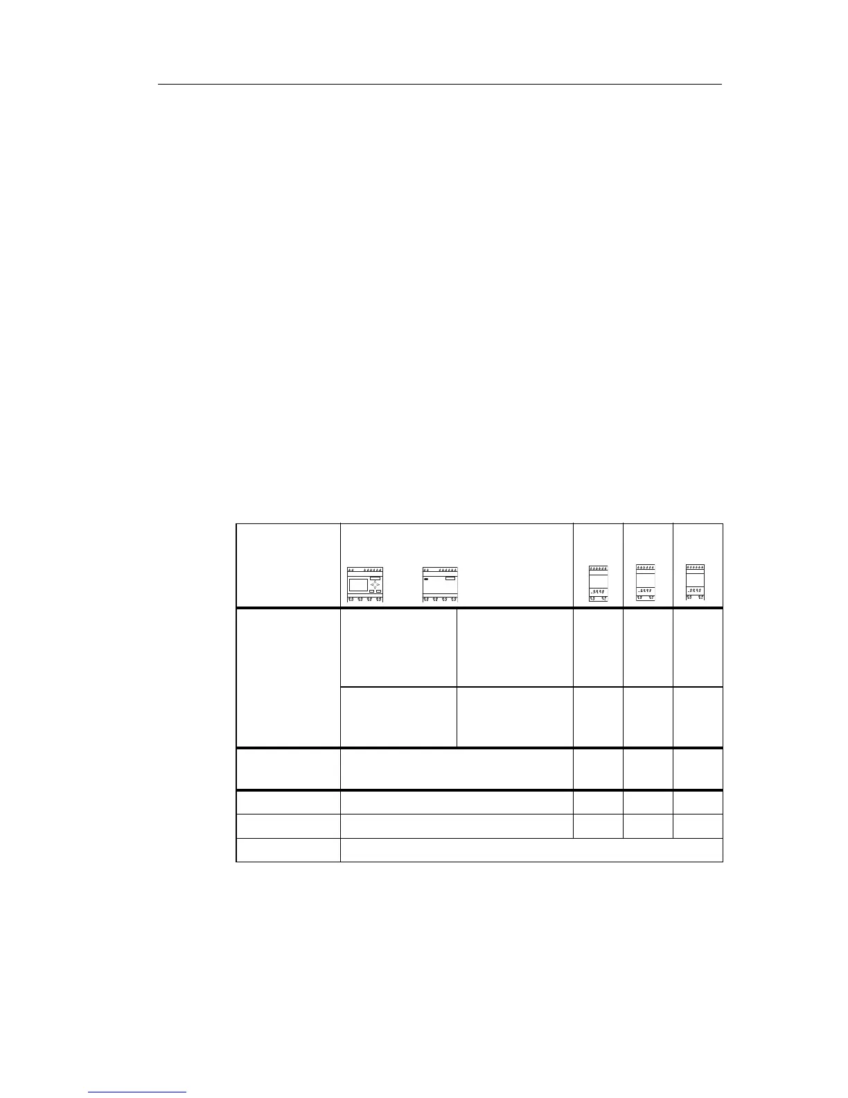
IDEC SmartRelay has the following conn
ectors:
Connectors IDEC SmartRelay base module DM AI
AO
Inputs FL1E-H12RCC/
FL1E-B12RCC,
FL1E-H12RCA/
FL1E-B12RCA
Two groups:
I1... I4 and
I5 ... I8
I9 ...
I24
AI1...
AI8
none
FL1E-H12RCE/
FL1E-B12RCE,
FL1E-H12SND
I1,I2, I3-I6, I7, I8
AI3,AI4 ...AI1,
AI2
I9 ...
I24
AI5...
AI8
Outputs Q1...Q4 Q5 ...
Q16
none AQ1,
AQ2
lo Logical ’0’ signals (off)
hi Logical ’1’ signals (on)
x An existing connection that is not used
DM: Digital module
AI: Analog input module
AO: Analog output module