EasyManua.ls Logo

IDEC FL1E-H12RCE

IDEC FL1E-H12RCE
356 pages
To Next Page IconTo Next Page
To Previous Page IconTo Previous Page
Loading...
Applications
272 IDEC SmartRelay Manual
Door control system with IDEC SmartRelaycircuit diagram
This is what the circuit diagram of the conventional solution
looks like.
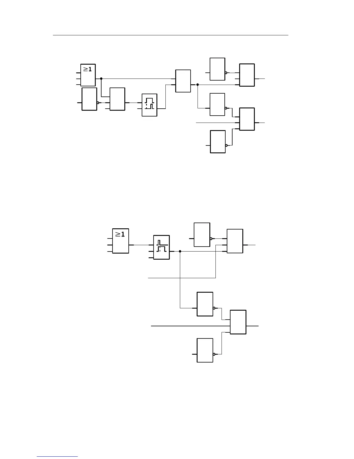
You can simplify this circuit if you make use of th
e IDEC
SmartRelay functions. You can use the off-delay function to
replace the latching relay and the on-delay. The block
diagram below illustrates this simplification:
&
1
1
1
&
I4
I3
I1
I2
x
Q2
Q1
x
10 s
Q1
Q2
Open
CloseClose
Motion
detector
Limit switch
Door open
Limit switch
Door closed
&
1
1
1
&
I4
I3
Q2
Q1
RS
I1
I2
1
I4
T=
4s
x
&
x
Q1
Q2
Open
Close
Phone: 800.894.0412 - Fax: 888.723.4773 - Web: www.clrwtr.com - Email: info@clrwtr.com

Table of Contents

Related product manuals