EasyManua.ls Logo

IDEC FL1E-H12RCE

IDEC FL1E-H12RCE
356 pages
To Next Page IconTo Next Page
To Previous Page IconTo Previous Page
Loading...
Applications
IDEC SmartRelay Manual 277
The circuit diagram for conventional solutions is as follows:
K1 K5
K5
S1
S0
K3K2
L1
N
S2
K1
v
>
S2
H1
K4
S3
v
>
K5
H2
K2 K4
Auxiliary circuit
Exhaust air Fresh air Operation Error
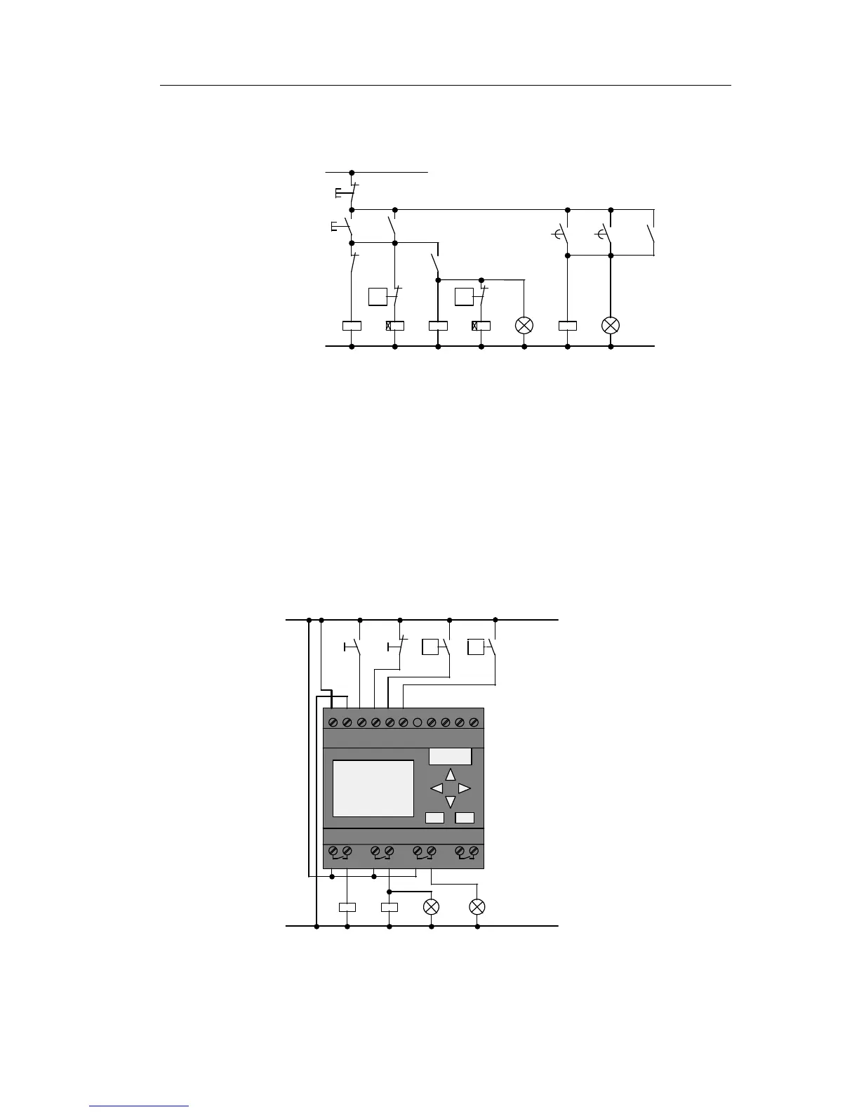
The fans are monitored by means of flow sensors. If no air
flow is registered within a short waiting time, the system is
switched off and an error message is output. This message
can be acknowledged by pressing the OFF button.
In addition to the flow sensors, the fan monitoring system
also r
equires
an evaluating circuit with several switching
devices. This evaluating circuit can be replaced by a single
IDEC SmartRelay unit.
Wiring of an air-conditioning system with FL1E-H12RCC
L1 N I1 I3 I6 I7 I8
Q1 Q2 Q3 Q4
K1 K2
S1
L1
N
S2 S3
v>
v>
H1 H2
S0
I4 I5I1 I2 I3I1 I2 I3
1 2 1 2 1 2 1 2
Exhaust
fan
Fresh-air
fan
Phone: 800.894.0412 - Fax: 888.723.4773 - Web: www.clrwtr.com - Email: info@clrwtr.com

Table of Contents

Related product manuals