Applications
292 IDEC SmartRelay Manual
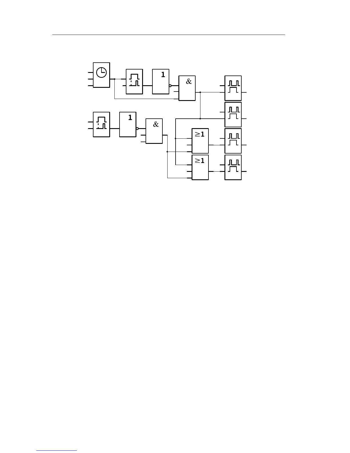
Block diagram of the IDEC SmartRelay solution
Advantages of the IDEC SmartRelay solution
• You can connect the lamps directly to the IDEC
SmartRelay, provided the power consumption does not
exceed the switching capacity of the various outputs.
Higher loads should be switched with a contactor relay.
• Connect the daylight control switch directly to an input of
the IDEC
SmartR
elay.
• You do not need an external timer, be
cause this function
is integrated in the IDEC SmartRelay.
• Due to the reduced amount of switchgear, you
can install
a smaller and space-saving distribution cabinet.
• Fewer devices are required
• The lighting system can be easily modified.
• Additional switching times can be se
t as required
(sequential circuit for the off pulses at the end of the day).
• The function of the daylight control switch
can be easily
applied to all lamps or to a modified group of lamps.
 Loading...
