Technical data
306 IDEC SmartRelay Manual
(1): When FL1E-H12SND or FL1B-M08B1S2 are switched on, signal 1 is sent to the
digital outputs for about 50 microseconds. Take this into account, especially when
using devices that react to short pulses.
(2) The maximum switching rate is only dependent on the switching program’s cycle
time.
Line length (shielded and twisted) 10 m
Error limit +/- 1.5% at full scale
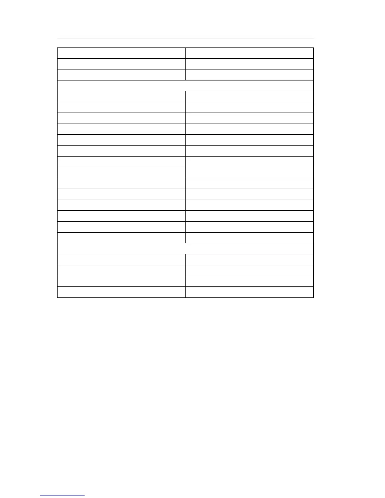
Digital outputs
Number 4
Output type Transistor, current-sourcing
(1)
Electrical isolation No
In groups of
Control of a digital input Yes
Output voltage Supply voltage
Output current max. 0.3 A
Short circuit-proof and overload-proof Yes
Short circuit current limitation Approx. 1 A
Derating none; across the entire temperature range
Short circuit-proof cos 1 not applicable for this module
Short circuit-proof cos 0.5 to 0.7 not applicable for this module
Parallel output circuit for power increase Not permitted
Protection of output relay (if desired)
Switching rate
(2)
Mechanical not applicable for this module
Electrical 10 Hz
Ohmic load/lamp load 10 Hz
Inductive load 0.5 Hz
FL1E-H12SND