IDEC SmartRelay installation and wiring
50 IDEC SmartRelay Manual
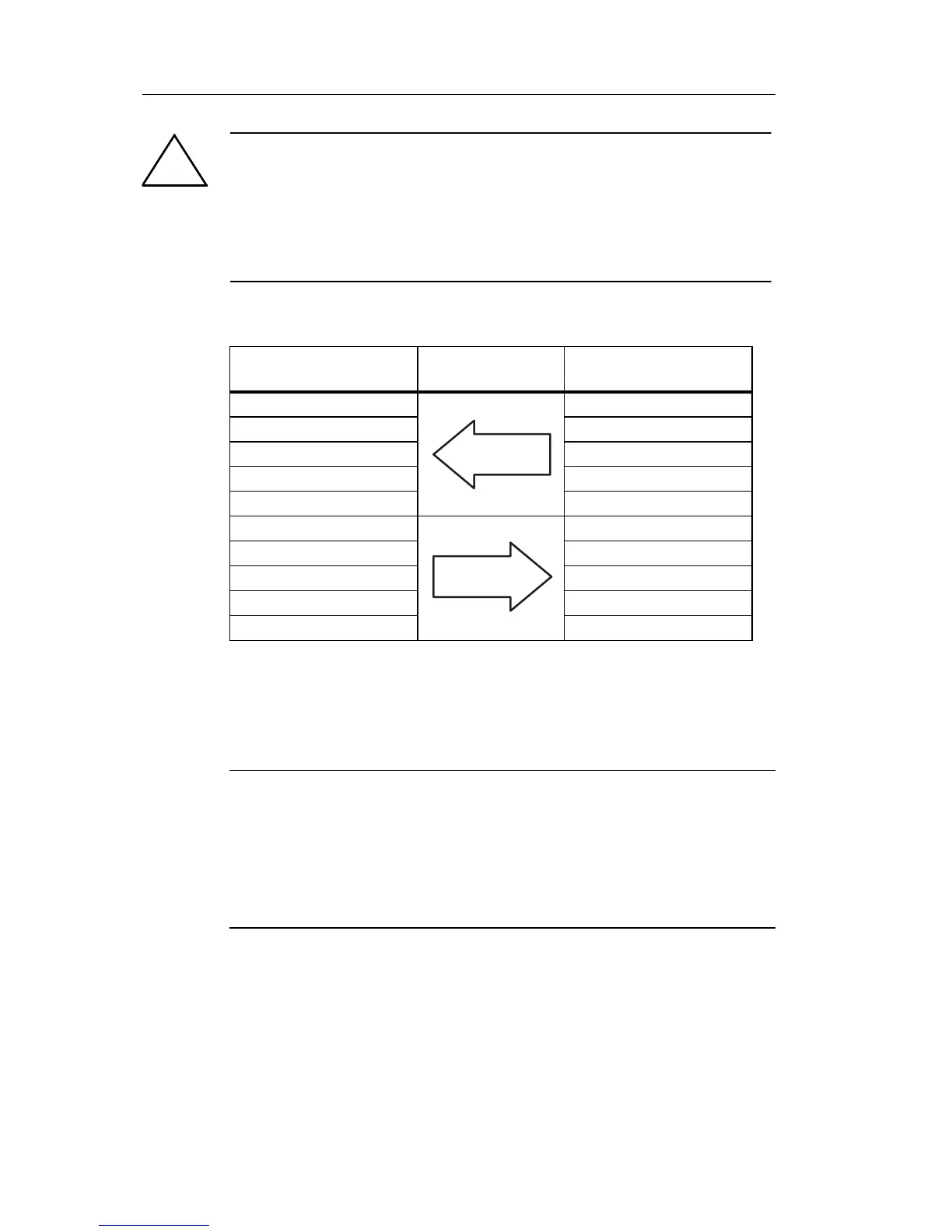
Logic Assignments
”n” depends on the plug–in position of the expansion module
relative to the IDEC SmartR
elay base module. It indicates
the number of the input or output in IDEC SmartRelay
program code.
Note
Ensure that there is enough space for the inputs/outputs of the AS
interface in the IDEC SmartRelay’s address space. If you are
already using more than 12 physical outputs or more than 20
physical inputs, it is no longer possible to operate the CM AS
interface!
Warning
The AS-Interface and IDEC SmartRelay systems must never be
connected together electrically!
Use safe isolation acc. to IEC 61131-2, EN 50178, UL 508, CSA
C22.2 No. 42.
IDEC SmartRelay sys-
tem
AS Interface system
Inputs Output data bits
I
n
D0
I
n+1
D1
I
n+2
D2
I
n+3
D3
Outputs Output data bits
Q
n
D0
Q
n+1
D1
Q
n+2
D2
Q
n+3
D3
 Loading...
