IDEC SmartRelay installation and wiring
IDEC SmartRelay Manual 55
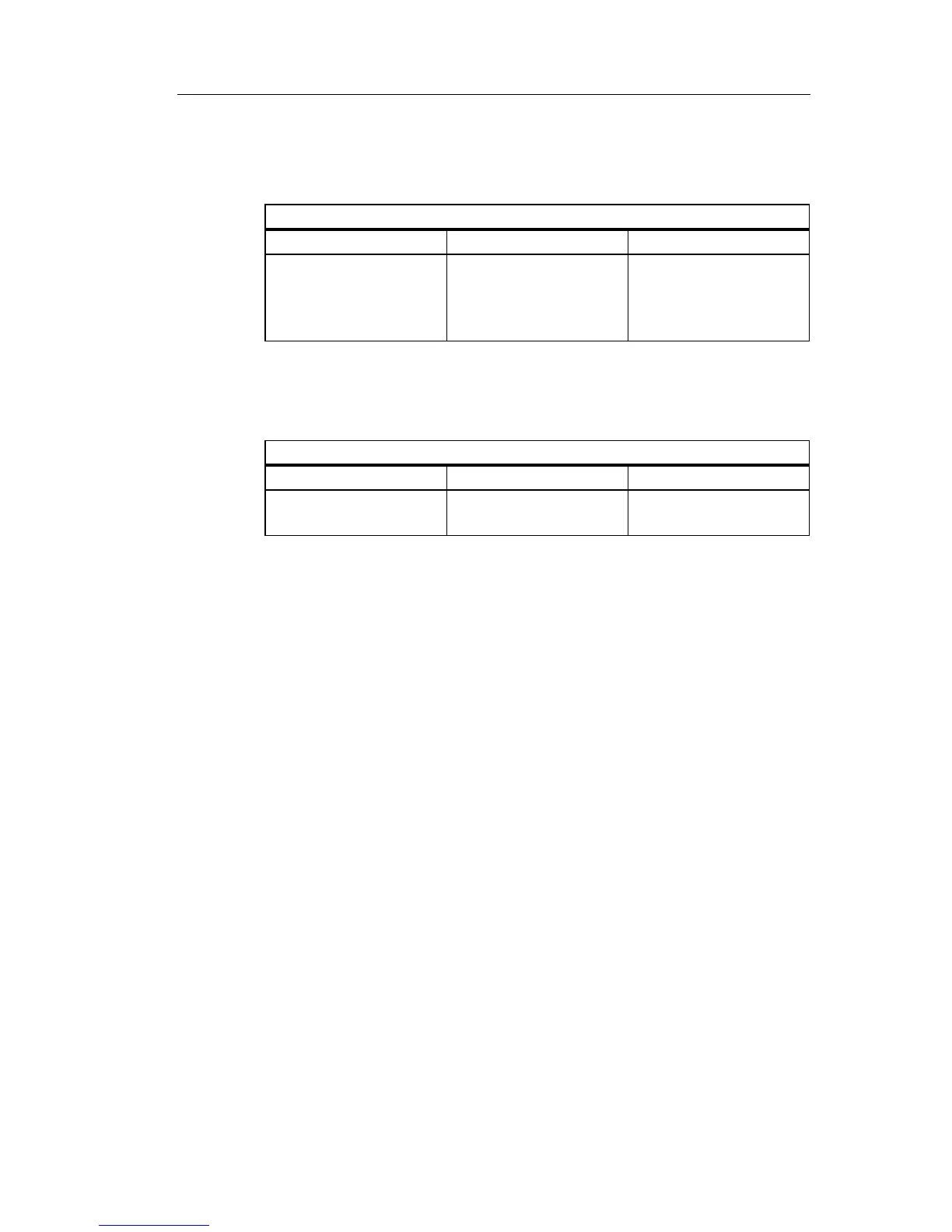
IDEC SmartRelay expansion modules, operating states
IDEC SmartRelay expansion modules have three operating
states: The LED (RUN/STOP) is lit green, red or orange.
CM AS Interface, communication states
The CM AS Interface has three communication states: The
LED is lit gr
een, red or flashes red/yellow.
CM AS Interface, behavior on communicat
ion failure
• If the AS Interface voltage fails, communication between
t
he IDEC SmartRelay system and the expansion
modules, which are arranged to the right of the IDEC
SmartRelay CM AS Interface expansion module, is
interrupted.
Recommendation: Position IDEC SmartRelay CM AS
Interf
ace on the far right side.
• If communication is interrupted, the switching outputs are
reset
after about 40 to 100 ms.
LED (RUN/STOP) is lit
Green (RUN) Red (STOP) Orange/Yellow
The expansion module
communicates with the
device to the left.
The expansion module
does not communicate
with the device to its
left.
Initialization phase of
the expansion module
LED AS-I is lit
Green Red Red/Yellow
AS Interface
communication OK
AS Interface
communication failed
Slave has address ”0”.
 Loading...
