EasyManuals Logo

IDEC FL1E-H12RCE User Manual

IDEC FL1E-H12RCE
356 pages
To Next Page IconTo Next Page
To Previous Page IconTo Previous Page
Page #85 background imageLoading...
Page #85 background image
Programming IDEC SmartRelay
IDEC SmartRelay Manual 71
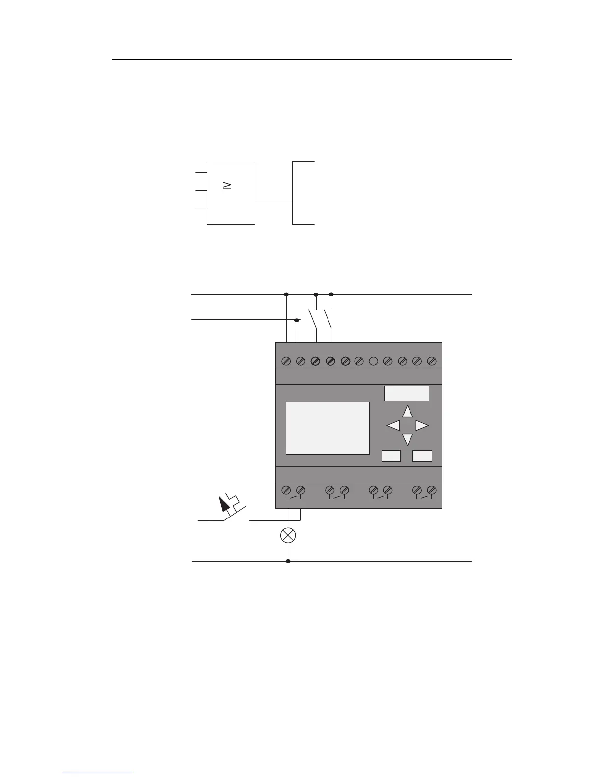
Circuit program
S1 is connected to the I1 and S2 to the I2 input connector of
the OR block.
The corresponding layout of the circuit program
in IDEC
SmartRelay:
I1
I2
x
Q1
1
Wiring
The corresponding wiring:
L1 N I4 I5 I6 I7 I8
Q1 Q2 Q3 Q4
L1
N
S1
S2
L
N
I1I1 I3I1I1
I2
1 2 1 2 1 2 1 2
S1 switches input I1, while S2 switches input I2. The load is
connected to the relay Q1.
Phone: 800.894.0412 - Fax: 888.723.4773 - Web: www.clrwtr.com - Email: info@clrwtr.com

Table of Contents

Questions and Answers:

Question and Answer IconNeed help?

Do you have a question about the IDEC FL1E-H12RCE and is the answer not in the manual?

IDEC FL1E-H12RCE Specifications

General IconGeneral
BrandIDEC
ModelFL1E-H12RCE
CategoryOther
LanguageEnglish

Related product manuals