Function Application
‑576‑
Note
Observe the following requirements when using the braking resistor or energy feedback
unit.
● Set F3–10 (Overexcitation gain) to 0. Failure to comply may lead to overcurrent
during operation.
● Set F3–23 (Overvoltage stall selection) to 0. Failure to comply may prolong the
deceleration time.
3.4.4 Speed Loop
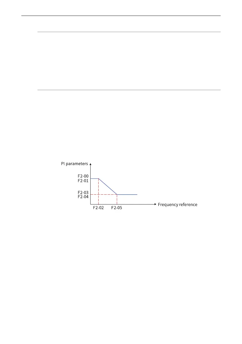
The speed loop PI parameters are divided into two groups: low speed and high speed.
When the running frequency is lower than F2‑02 (Switchover frequency 1), the speed
loop PI parameters are adjusted by F2‑00 and F2‑01. When the running frequency is
higher than F2‑05 (Switchover frequency 2), the speed loop PI parameters are
adjusted by F2‑03 and F2‑04. If the running frequency is between switchover
frequency 1 and switchover frequency 2, the speed loop PI parameters switch linearly
between the two groups of PI parameters.
Figure 3‑44 Switchover of speed loop PI parameters
You can adjust the dynamic speed response characteristic of vector control by setting
the proportional factor and integral time of the speed regulator.
Increasing the proportional gain or shortening the integral time can speed up
dynamic response of the speed loop. However, excessively large proportional gain or
excessively short integral time may cause system oscillation.
If the factory settings cannot meet your requirements, increase the proportional gain
first to ensure that the system does not oscillate, and then reduce the integral time to
ensure quick system response and small overshoot.

 Loading...


