Function Application
‑495‑
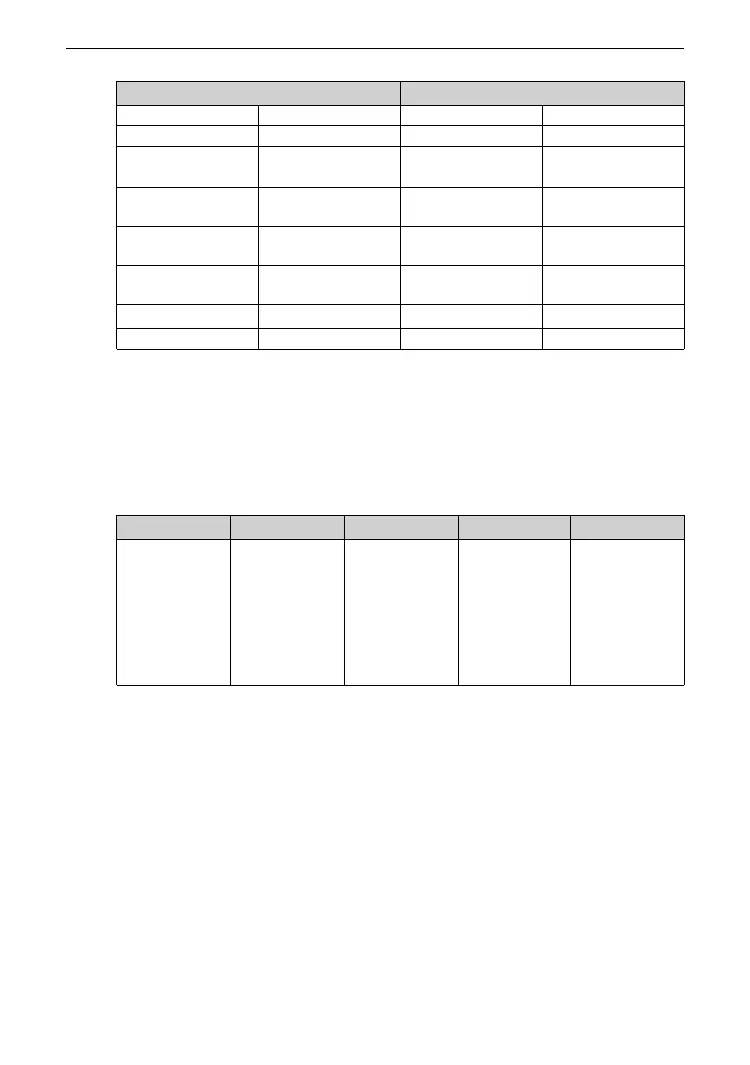
Master Command Slave Response
ADDR 01H ADDR 01H
CMD 06H CMD 06H
Parameter address
high‑order bits
20H
Parameter address
high‑order bits
20H
Parameter address
low‑order bits
00H
Parameter address
low bits
00H
Data content high‑
order bits
00H
Data content high
bits
00H
Data content low‑
order bits
02H
Data content low
bits
02H
CRC high‑order bits
03H
CRC high‑order bits
03H
CRC low‑order bits
CBH
CRC low‑order bits
CBH
3.1.1.4 Setting Commands Through Terminals
Set F0‑02 to 1 to use terminals to start and stop the AC drive.
Set F4‑11 to select a terminal control mode. The AC drive supports four terminal
control modes: two‑wire mode 1, two‑wire mode 2, three‑wire mode 1, and three‑wire
mode 2.
Para.
Function
Default Value Range
Description
F4‑11
Terminal control
mode
0
0: Two‑wire
mode 1
1: Two‑wire
mode 2
2: Three‑wire
mode 1
3: Three‑wire
mode 2
Four modes to
control the AC
drive operation
by using
external
terminals
You can use any one of multi‑functional input terminals DI1 to DI10 as external input
terminals. That is, set parameters F4‑00 to F4‑09 to select functions for input
terminals DI1 to DI10. For details about function definitions, see "F4‑00 (DI1) to F4‑09
(DI10) Terminal Function" in "
1.1 List of Function Parameters
"
on page 7
.
Two-wire mode 1
Set F4‑11 to 0. This is the most commonly used two‑wire mode.
For example, DI1 is assigned with the forward run function, and DI2 is assigned with
the reverse run function. Connect the forward run switch to DI1 and the reverse run
switch to DI2.

 Loading...


