Function Application
‑664‑
3.7.5 Overload Protection
To provide effective protection for motors with different loads, set the motor overload
protection gain properly based on the overload capacity of a motor. The motor
overload protection curve is an inverse time lag curve, as shown in the following
figure.
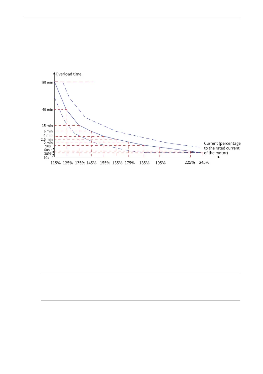
Figure 3‑82 Inverse time lag curve of motor overload protection
When the motor running current reaches 175% of the rated motor current and lasts
for 2 minutes, E11.00 (motor overload) is reported. When the motor running current
reaches 115% of the rated motor current and lasts for 80 minutes, E11.00 is reported.
1. Example 1
● Assume that the rated motor current is 100 A. If F9‑01 is set to 1.00, according to
the preceding figure, the AC drive reports a motor overload alarm (E11.00) after
the motor runs at 125% of 100 A (125 A) continuously for 40 minutes.
● If F9‑01 is set to 1.20, according to the preceding figure, the AC drive reports a
motor overload alarm (E11.00) after the motor runs at 125% of 100 A (125 A)
continuously for 48 minutes (40 x 1.2).
Note
The maximum overload time is 80 minutes and the minimum overload time is 10 seconds.
2. Example 2
Assume that the application requires an overload alarm when the motor runs at
150% of rated motor current for 2 minutes. According to the motor overload
protection curve, 150% (I) of the rated motor current is between 145% (I1) and
155% (I2) of the rated motor current. As the overload time is 6 minutes (T1) at the

 Loading...


