EasyManuals Logo

Intel S2600CW User Manual

Intel S2600CW
210 pages
To Next Page IconTo Next Page
To Previous Page IconTo Previous Page
Page #112 background imageLoading...
Page #112 background image
Intel® Server Board S2600CW Connector/Header Locations and Pin-outs
Intel® Server Board S2600CW Family TPS
98 Revision 2.4
7. Intel® Server Board S2600CW Connector/Header
Locations and Pin-outs
7.1 Power Connectors
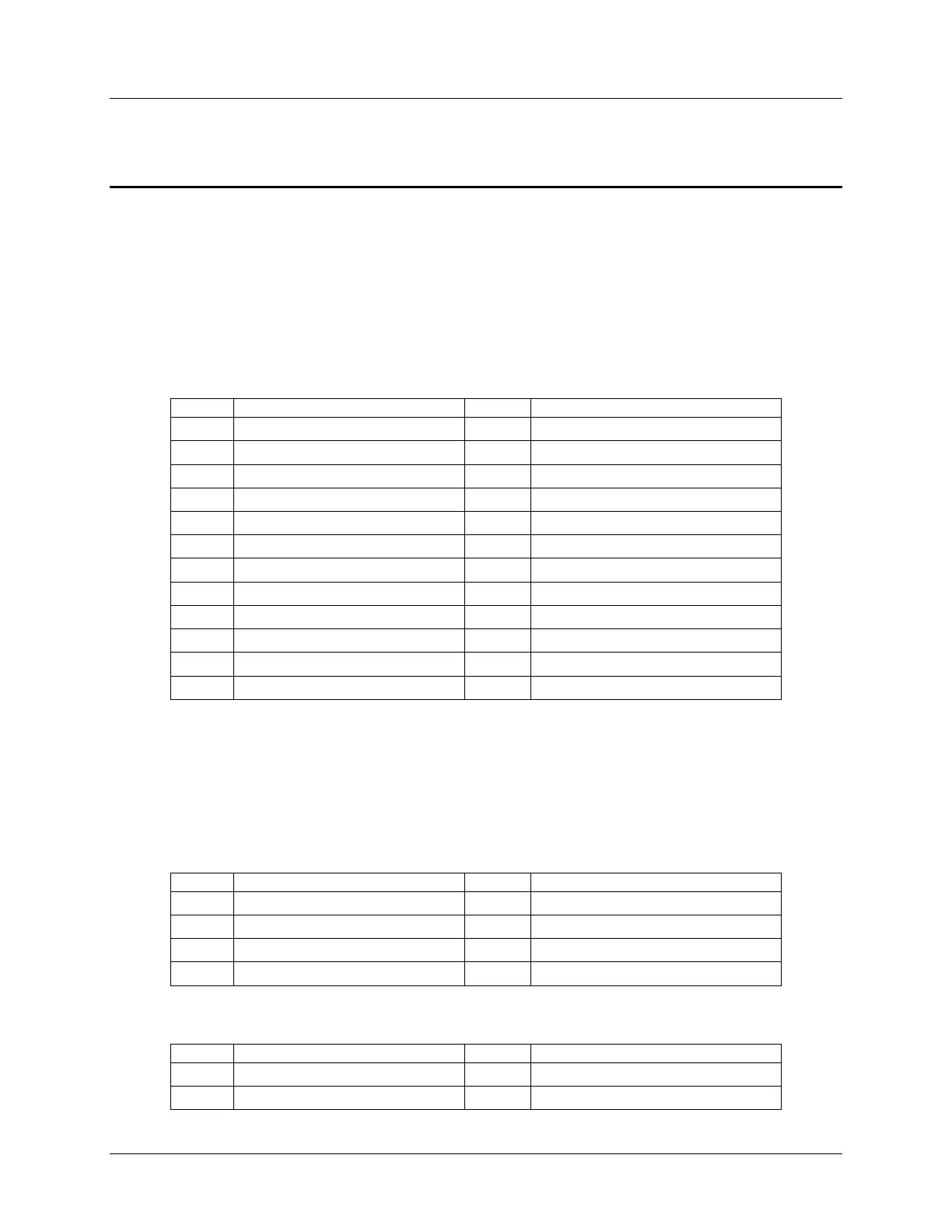
7.1.1 Main Power Connector
Main server board power is supplied by one 12-pin power connector. The connector is labeled
as “MAIN PWR” on the left bottom of the server board. The following table provides the
pin-out for “MAIN PWR” connector.
Table 14. Main Power Connector Pin-out
Pin
Signal Name
Pin
Signal Name
1
P3V3
13
P3V3
2
P3V3
14
N12V
3
GND
15
GND
4
P5V
16
FM_PS_EN_PSU_ON
5
GND
17
GND
6
P5V
18
GND
7
GND
19
GND
8
PWRGD_PS_PWROK_PSU_R1
20
NC_PS_RES_TP
9
P5V_STBY_PSU
21
P5V
10
P12V
22
P5V
11
P12V
23
P5V
12
P3V3
24
GND
7.1.2 CPU Power Connectors
On the server board are two white 8-pin CPU power connectors labeled “CPU_1 PWR” and
“CPU_2 PWR”. The following table provides the pin-out for both connectors.
Table 15. CPU_1 Power Connector Pin-out
Pin
Signal Name
Pin
Signal Name
1
GND
5
P12V1
2
GND
6
P12V1
3
GND
7
P12V3A
4
GND
8
P12V3A
Table 16. CPU_2 Power Connector Pin-out
Pin
Signal Name
Pin
Signal Name
1
GND
5
P12V2
2
GND
6
P12V2

Table of Contents

Other manuals for Intel S2600CW

Questions and Answers:

Question and Answer IconNeed help?

Do you have a question about the Intel S2600CW and is the answer not in the manual?

Intel S2600CW Specifications

General IconGeneral
BrandIntel
ModelS2600CW
CategoryServer Board
LanguageEnglish

Related product manuals