Intel® Server Board S2600CW Family TPS Intel® Light Guided Diagnostics
Revision 2.4
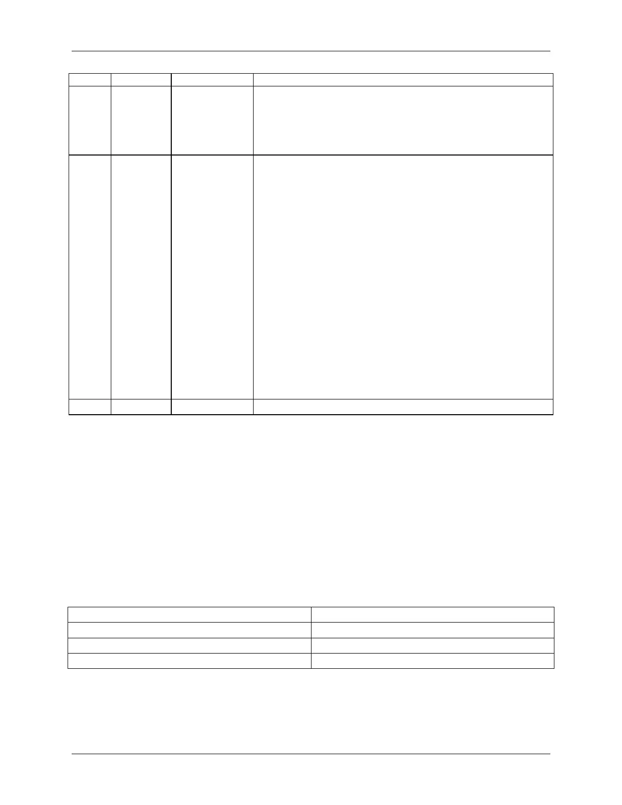
5. Power Unit Redundancy sensor – Insufficient resources offset
(indicates not enough power supplies present).
6. In non-sparing and non-mirroring mode if the threshold of
correctable errors is crossed within the window.
recoverable
Fatal alarm – system has failed or shutdown:
1. CPU CATERR signal asserted.
2. MSID mismatch detected (CATERR also asserts for this case).
3. CPU 1 is missing.
4. CPU ThermalTrip.
5. No power good – power fault.
6. DIMM failure when there is only 1 DIMM present and hence no
good memory present.
7. Runtime memory uncorrectable error in non-redundant mode
1
.
8. DIMM Thermal Trip or equivalent.
9. SSB Thermal Trip or equivalent.
10. CPU ERR2 signal asserted.
11. BMC\Video memory test failed. (Chassis ID shows blue/solid-on
for this condition).
12. Both uBoot BMC FW images are bad. (Chassis ID shows
blue/solid-on for this condition).
13. 240VA fault
Note:
* When the server is powered down (transitions to the DC-off state or S5), the BMC is still on standby power and
retains the sensor and front panel status LED state established before the power-down event. If the system status
is normal when the system is powered down (the LED is in a solid green state), the system status LED is off.
9.4.3 POST Code Diagnostic LEDs
During the system boot process, the BIOS executes a number of platform configuration
processes, each of which is assigned a specific hex POST code number. As each configuration
routine is started, the BIOS displays the given POST code to the POST code diagnostic LEDs
on the back edge of the server boards. To assist in troubleshooting a system hang during the
POST process, you can use the diagnostic LEDs to identify the last POST process executed.
Table 39. POST Code Diagnostic LEDs
A. Diagnostic LED #7 (MSB LED)
H. Diagnostic LED #0 (LSB LED)