Intel® Server Board S2600CW Family TPS Power Supply Specification Guidelines
Revision 2.4
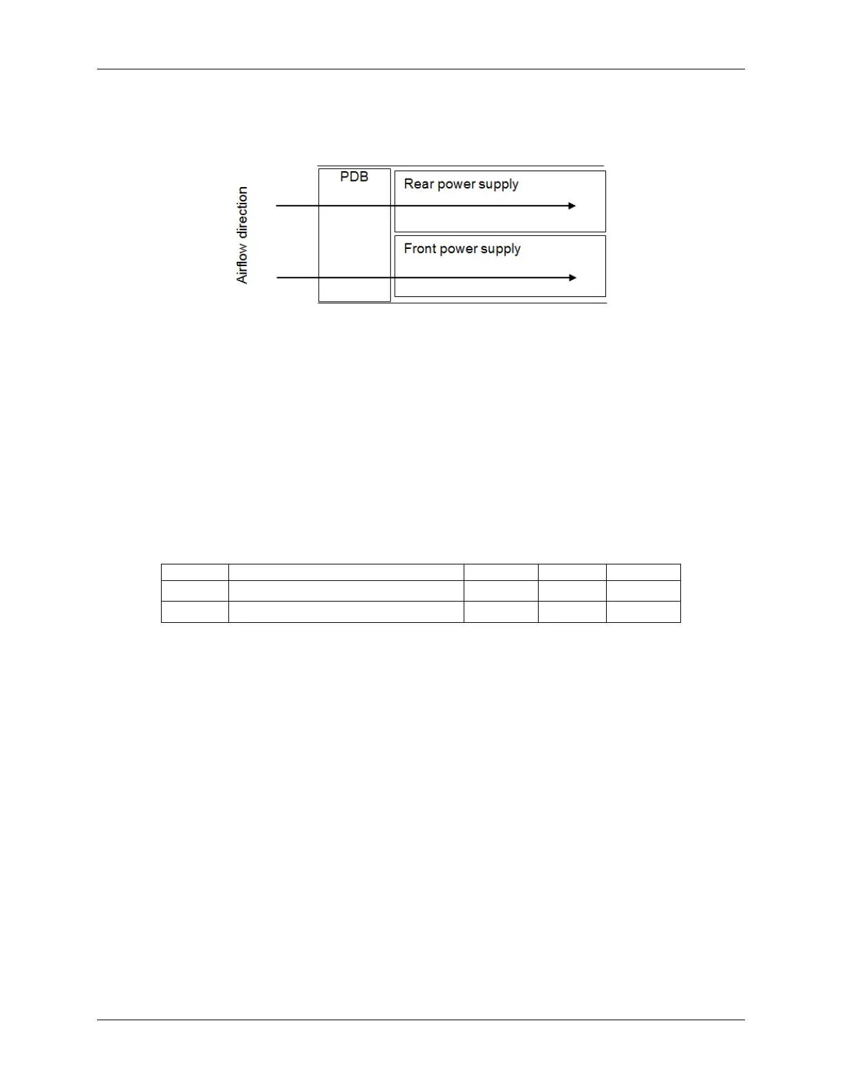
The amount of cooling airflow that will be available to the DC/DC converters is to be no less
than 1.2M/s.
Figure 31. Airflow Diagram
10.3.1.2 DC/DC Converter Cooling
The DC/DC converters on the power distribution board are in series with the airflow path with
the power supplies.
10.3.1.3 Temperature Requirements
The PDB operates within all specified limits over the Top temperature range. Some amount of
airflow shall pass over the PDB.
Table 61. Thermal Requirements
op
Operating temperature range.
non-op
Non-operating temperature range.
10.3.1.4 Efficiency
Each DC/DC converter shall have a minimum efficiency of 85% at 50% ~ 100% loads and
over +12V line voltage range and over temperature and humidity range.
10.3.2 DC Output Specification
10.3.2.1 Input Connector (Power Distribution Mating Connector)
The power distribution provides two power pin, a card edge output connection for power and
signal that is compatible with a 2x25 Power Card Edge connector (equivalent to 2x25 pin
configuration of the FCI power card connector 10035388-102LF). The FCI power card edge
connector is a new version of the PCE from FCI used to raise the card edge by 0.031” to allow
for future 0.093” PCBs in the system. The card edge connector has no keying features; the
keying method is accomplished by the system sheet metal.