Intel® Server Board S2600CW Family TPS
Intel® Server Board S2600CW Connector/Header Locations and Pin-outs
Revision 2.4
7.2 Front Panel Header and Connectors
The server board includes several connectors that provide various possible front panel
options. This section provides a functional description and pin-out for each connector.
7.2.1 Front Panel Header
Included on the left edge of the server board is a 24-pin SSI-compatible front panel header
which provides various front panel features including:
Power/Sleep Button
System ID Button
NMI Button
NIC Activity LEDs
Hard Drive Activity LEDs
System Status LED
System ID LED
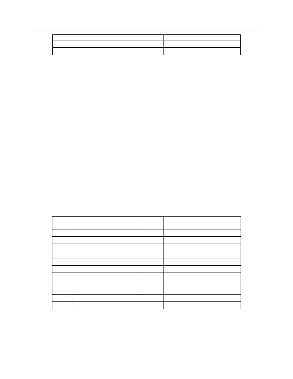
The following table provides the pin-out for this 24-pin header.
Table 17. Front Panel Header Pin-out
FP_LED_STATUS_GREEN_BUF_N
FP_LED_STATUS_AMBER_BUF_N
LED_NIC_LINK0_LNKUP_BUF_N
LED_NIC_LINK1_LNKUP_BUF_N
7.2.2 Front Panel USB Connector
The server board includes a 20-pin connector, which when cabled, can provide up to two USB
3.0 ports to a front panel. The following table provides the connector pin-out.