EasyManuals Logo
Home>Intel>Server Board>S2600CW

Intel S2600CW User Manual

Intel S2600CW
210 pages
To Next Page IconTo Next Page
To Previous Page IconTo Previous Page
Page #114 background imageLoading...
Page #114 background image
Intel® Server Board S2600CW Connector/Header Locations and Pin-outs
Intel® Server Board S2600CW Family TPS
100 Revision 2.4
Table 18. Front Panel USB 3.0 Connector Pin-out
Pin
Signal Name
Pin
Signal Name
1
P5V_AUX_USB_FP_USB3
key
KEY
2
USB3_01_FB_RX_DN
19
P5V_AUX_USB_FP_USB3
3
USB3_01_FB_RX_DP
18
USB3_00_FB_RX_DN
4
GND
17
USB3_00_FB_RX_DP
5
USB3_01_FB_TX_DN
16
GND
6
USB3_01_FB_TX_DP
15
USB3_00_FB_TX_DN
7
GND
14
USB3_00_FB_TX_DP
8
USB2_13_FB_DN
13
GND
9
USB2_13_FB_DP
12
USB2_8_FB_DN
10
TP_FM_OC5_FP_R_N
11
USB2_8_FB_DP
7.3 On-board Storage Connectors
The server board provides connectors for support of several storage device options. This
section provides a functional overview and pin-out of each connector.
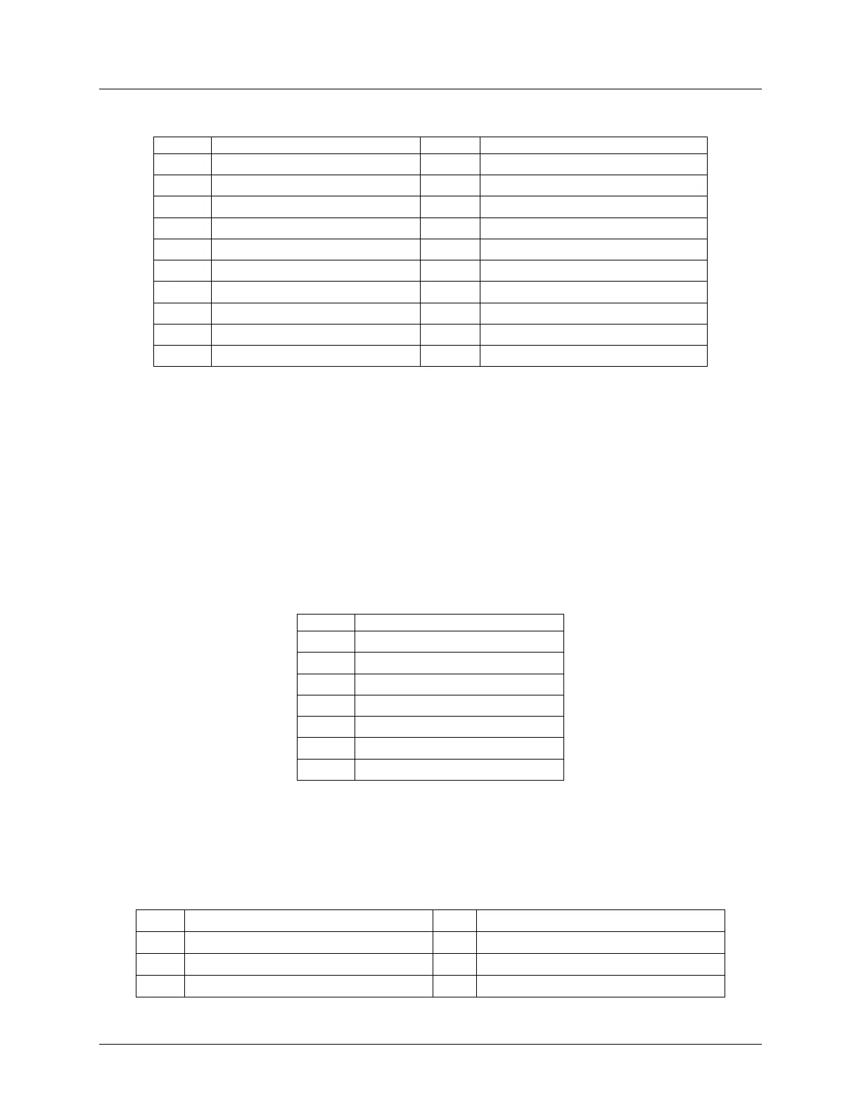
7.3.1 SATA 6Gbps Connectors
The server board includes two 7-pin SATA connectors capable of transfer rates of up to
6Gbps. The following table provides the pin-out for both connectors.
Table 19. SATA 6Gbps Connector Pin-out
Pin
Signal Name
1
GND
2
SATA_TX_P
3
SATA_TX_N
4
GND
5
SATA_RX_N
6
SATA_RX_P
7
GND
The server board also includes two mini-SAS HD ports, each supporting four SATA 6Gbps
transfer rates. The following table provides the pin-out for both connectors.
Table 20. Mini-SAS HD Connectors for SATA 6Gbps Pin-out
Pin
Signal Name
Pin
Signal Name
1A1
TP_SAS1_BACKPLANE_TYPE
2A1
TP_SAS0_BACKPLANE_TYPE
1B1
GND
2B1
GND
1C1
SGPIO_SSATA_DATAOUT0_R1
2C1
SGPIO_SATA_DATAOUT0_R1

Table of Contents

Other manuals for Intel S2600CW

Questions and Answers:

Question and Answer IconNeed help?

Do you have a question about the Intel S2600CW and is the answer not in the manual?

Intel S2600CW Specifications

General IconGeneral
BrandIntel
ModelS2600CW
CategoryServer Board
LanguageEnglish

Related product manuals