Power Supply Specification Guidelines Intel® Server Board S2600CW Family TPS
130 Revision 2.4
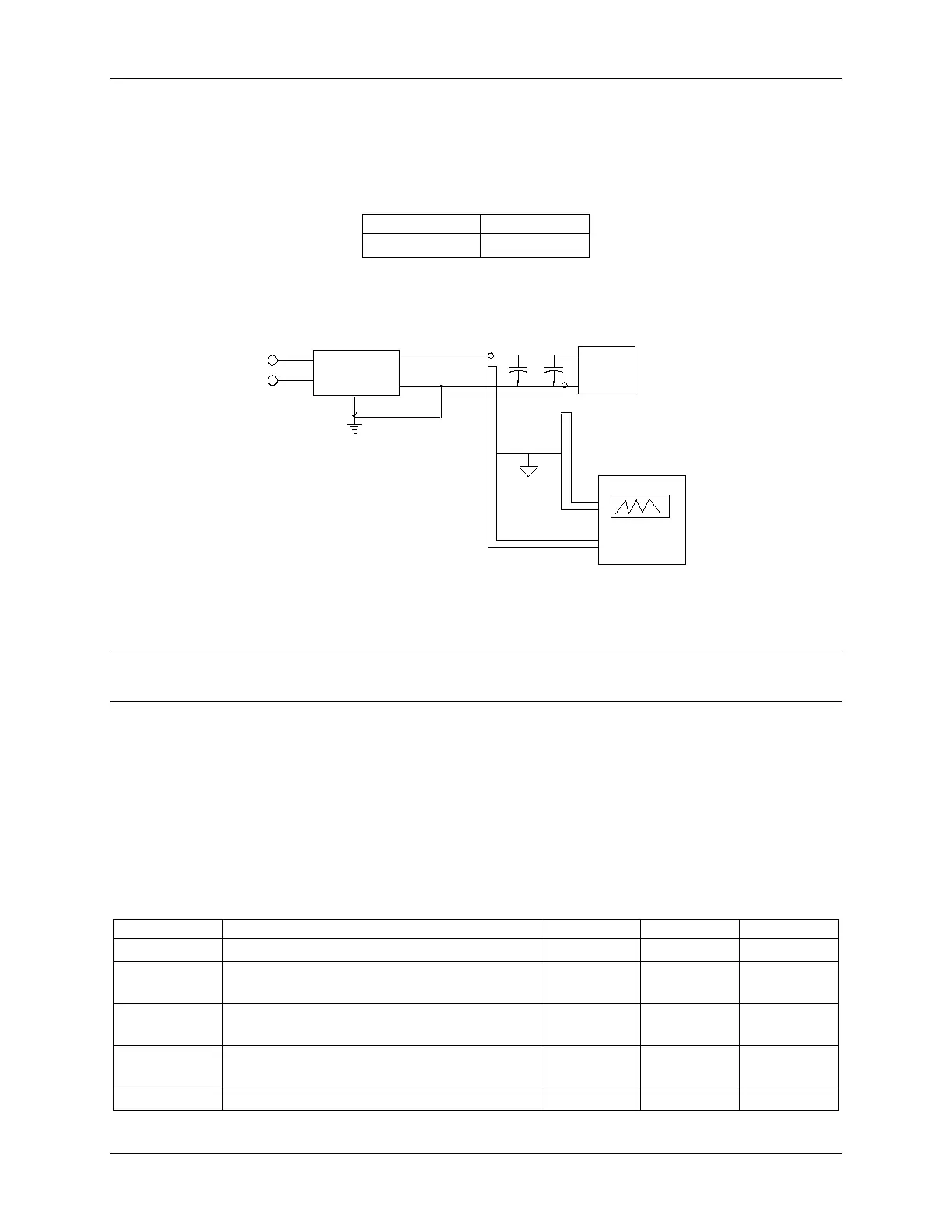
A 10µF tantalum capacitor in parallel with a 0.1µF ceramic capacitor is placed at the point of
measurement.
Table 54. Ripples and Noise
The test setup shall be as shown below.
AC HOT
POWER SUPPLY
AC NEUTRAL
V
OUT
RETURN
V
AC GROUND
LOAD
SCOPE
LOAD MUST BE
ISOLATED FROM
THE GROUND OF
THE POWER
SUPPLY
10uF
.1uF
GENERAL NOTES:
1. LOAD THE OUTPUT WITH ITS MINIMUM
LOAD CURRENT.
2. CONNECT THE PROBES AS SHOWN.
3. REPEAT THE MEASUREMENTS WITH THE
MAXIMUM LOAD ON THE OUTPUT.
SCOPE NOTE:
USE A TEKTRONIX 7834 OSCILLOSCOPE WITH 7A13 AND
DIFFERENTIAL PROBE P6055 OR EQUIVALENT.
Figure 27. Differential Noise Test Setup
Note: When performing this test, the probe clips and capacitors should be located close to the
load.
10.2.4.12 Timing Requirements
These are the timing requirements for the power supply operation. The output voltages must
rise from 10% to within regulation limits (T
vout_rise
) within 5 to 70ms. For 12VSB, it is allowed to
rise from 1.0 to 25ms. All outputs must rise monotonically. Table below shows the timing
requirements for the power supply being turned on and off by the AC input, with PSON held
low and the PSON signal, with the AC input applied.
Table 55. Timing Requirements
sb_on_delay
Delay from AC being applied to 12VSB being
within regulation.
ac_on_delay
Delay from AC being applied to all output
voltages being within regulation.
vout_holdup
Time 12Vl output voltage stay within regulation
after loss of AC.
pwok_holdup
Delay from loss of AC to de-assertion of PWOK