List of Figures
Figure 1. Intel® Compute Module HNS7200AP Product Family ........................................................................................ 1
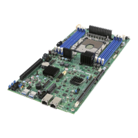
Figure 2. Intel® Server Board S7200AP Product Family .................................................................................................... 1
Figure 3. Intel® Server Board S7200AP Rear Connectors .................................................................................................. 7
Figure 4. Intel® Compute Module HNS7200AP Rear Connectors ..................................................................................... 8
Figure 5. Power Docking Board Features ............................................................................................................................. 8
Figure 6. 6G SATA Bridge Board Features ............................................................................................................................ 8
Figure 7. Intel® Server Board S7200AP Features ................................................................................................................ 9
Figure 8. Intel® Server Board S7200APR ............................................................................................................................. 9
Figure 9. Intel® Light-Guided Diagnostic LEDs – Server Board ....................................................................................... 10
Figure 10. Configuration and Recovery Jumpers ............................................................................................................. 11
Figure 11. Cable Routing ...................................................................................................................................................... 13
Figure 12. Removing the Air Duct ....................................................................................................................................... 14
Figure 13. Installing the Air Duct ........................................................................................................................................ 15
Figure 14. Processor Heatsink Module (PHM) and Processor Socket Reference Diagram ......................................... 16
Figure 15. Processor Reference Diagram - Top and Bottom Views of Processor ......................................................... 17
Figure 16. Grasping the Heatsink Correctly ...................................................................................................................... 18
Figure 17. Placing the Processor Heat Sink on to a Flat Surface ................................................................................... 18
Figure 18. Alignment Features ............................................................................................................................................ 19
Figure 19. Processor Carrier Assembly .............................................................................................................................. 20
Figure 20. Processor Carrier Clip Sub-Assembly.............................................................................................................. 20
Figure 21. Orienting Processor Carrier Clip Sub-assembly to Heat Sink ...................................................................... 21
Figure 22. Processor Heat Sink Module (PHM) ................................................................................................................. 21
Figure 23. Processor Heat Sink Location ........................................................................................................................... 22
Figure 24. Plastic processor socket cover removal .......................................................................................................... 23
Figure 25. PHM Alignment to Bolster Plate ....................................................................................................................... 24
Figure 26. Correct Placement .............................................................................................................................................. 25
Figure 27. Installing the PHM .............................................................................................................................................. 25
Figure 28. Uninstalling the PHM ......................................................................................................................................... 26
Figure 29. Plastic processor socket cover Installation .................................................................................................... 26
Figure 30. PHM Disassembly ............................................................................................................................................... 27
Figure 31. Releasing the Processor Carrier Clip from the Heat Sink ............................................................................. 27
Figure 32. Releasing Processor from Carrier ..................................................................................................................... 28
Figure 33. 1U LACC Assembly ............................................................................................................................................. 29
Figure 34. 1U LACC Assembly installed in the system .................................................................................................... 29
Figure 35. Disconnect the Pump Cable (Fan Header J6J2) ............................................................................................. 30
Figure 36. Remove LACC brackets #1 ................................................................................................................................ 30
Figure 37. Remove LACC brackets #2 ................................................................................................................................ 31
Figure 38. Remove LACC brackets #3 ................................................................................................................................ 31
Figure 39. Remove Cold Plate Assembly ........................................................................................................................... 32
Figure 40. Lift out LACC Assembly ..................................................................................................................................... 32
Figure 41. Releasing CPU and Carrier from Cold Plate .................................................................................................... 33
Figure 42. 1U LACC Assembly ............................................................................................................................................. 33
Figure 43. Install CPU and Carrier to Cold LACC Cold Plate ........................................................................................... 34
Figure 44. Install the LACC assembly into the system ..................................................................................................... 35
Figure 44. Install the LACC assembly into the system ..................................................................................................... 35
Figure 45. Install brackets #1 .............................................................................................................................................. 35
Figure 46. Install LACC brackets #2 .................................................................................................................................... 36
Figure 47. Install LACC brackets #3 .................................................................................................................................... 36
Figure 48. Connect the Pump Cable (fan header J6J2) ................................................................................................... 37
Figure 49. Removing Riser 1 ................................................................................................................................................ 38
Figure 50. Installing Riser 1 ................................................................................................................................................. 39
Figure 51. Removing Riser 2 ................................................................................................................................................ 39
Figure 52. Installing Riser 2 ................................................................................................................................................. 40
Figure 53. Installing the PCIe* Add-In Card– Step 1 ........................................................................................................ 40
Figure 54. Installing the PCIe* Add-In Card – Step 2 ....................................................................................................... 41
Figure 55. Installing the PCIe* Add-In Card – Step 3 ....................................................................................................... 41
Figure 56. Removing the PCIe* Add-In Card – Step 1 ...................................................................................................... 42