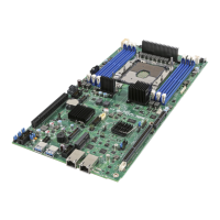
WARNING: Damage to the processor heat sink may occur when grasping the heat sink by the longer sides
and squeezing fins together. Processor heat sinks should only be grasped using the shorter edges of the
heat sink as shown in the following illustration.
Figure 16. Grasping the Heatsink Correctly
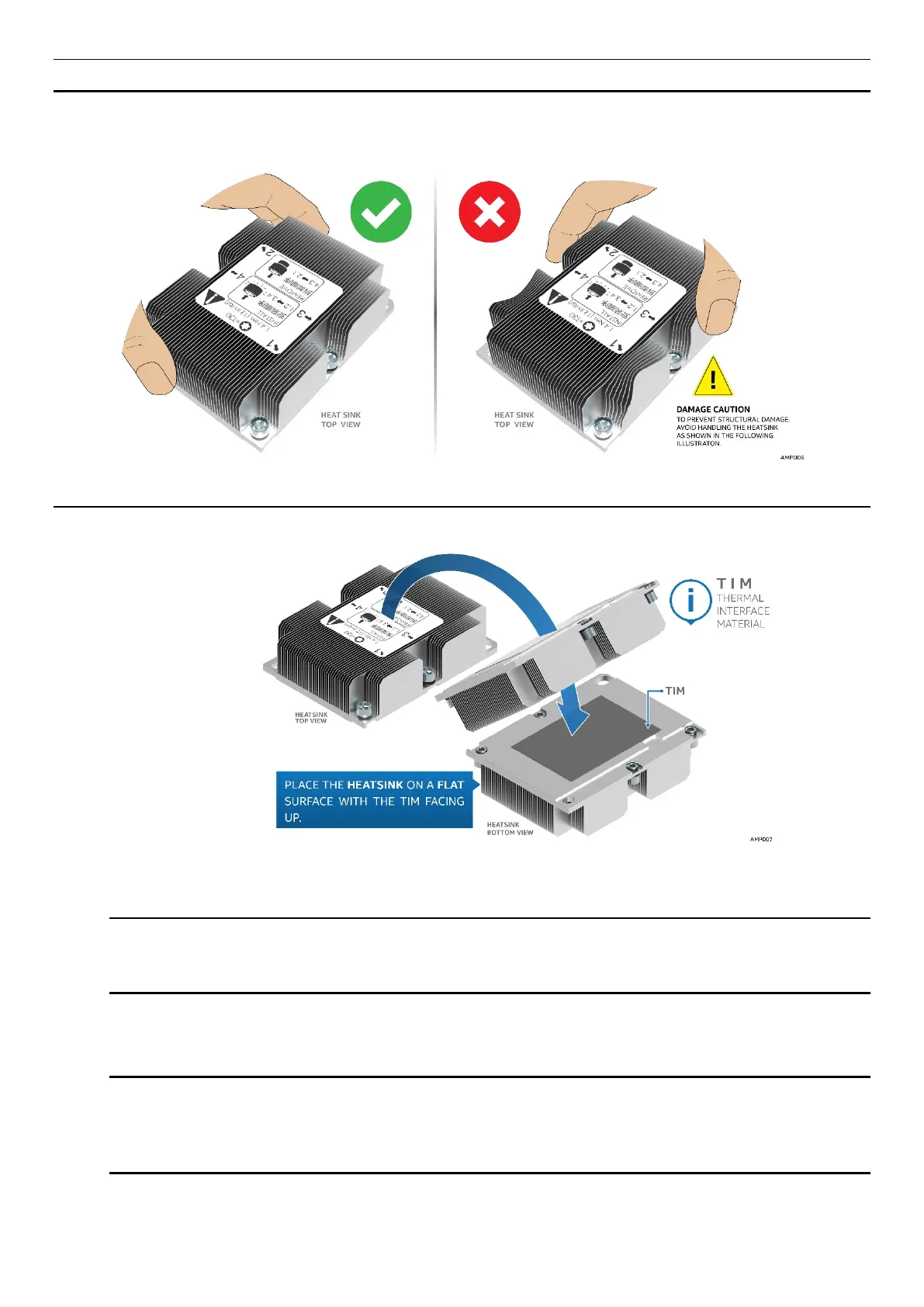
1. Remove the heat sink from its packaging. With the thermal interface material (TIM) facing up, place the
heat sink on to a flat surface as shown in the following illustration.
Figure 17. Placing the Processor Heat Sink on to a Flat Surface
CAUTION: Do not touch the sensitive contacts on the bottom side of the processor at any time
during PHM assembly or installation. In addition, the pins inside the processor socket are
extremely sensitive. A damaged processor socket may produce unpredictable system errors
2. If present, carefully remove the plastic protective cover from the bottom side of the processor.
NOTE: The PHM and processor socket include several alignment features as shown in the
following illustration to ensure proper assembly and installation. Care should be taken to ensure
components are accurately assembled and the PHM is oriented correctly to the processor socket
prior to installation.