2.4 Processor Assembly Installation and Removal
2.4.1 Assembling the Processor Heat Sink Module (PHM)
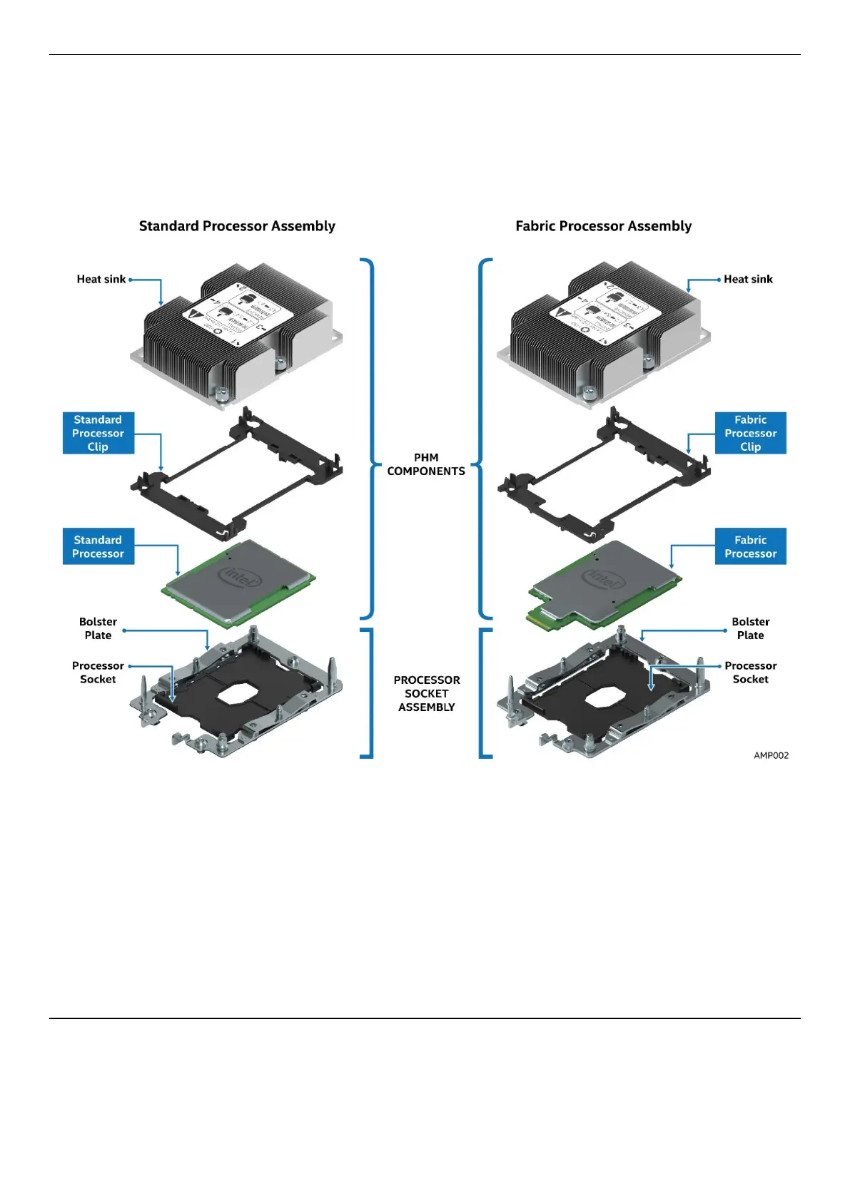
The processor heat sink module (PHM) refers to the sub-assembly where the heat sink and processor are
attached together prior to installation onto the server board.
Figure 14. Processor Heatsink Module (PHM) and Processor Socket Reference Diagram
Procedures described in the following sections must be followed in the order specified to properly
assemble the PHM, install it to, or remove it from the server board. These instructions assume that all the
PHM components are new and the thermal interface material (TIM) is already applied to the bottom of the
heat sink.
Required Tools:
• T-30 Torx screwdriver
• Flat head screwdriver
• Adequate ESD protective gear (wrist strap, ESD mat)
CAUTION: Refer to the “Warning” section at the beginning of this document for detailed ESD
precautions.
NOTE: Fabric supported processor models require the use of a Fabric Carrier assembly. Fabric Carrier
assemblies are sold separately and can be obtained by ordering the following Intel Accessory Kit - iPC