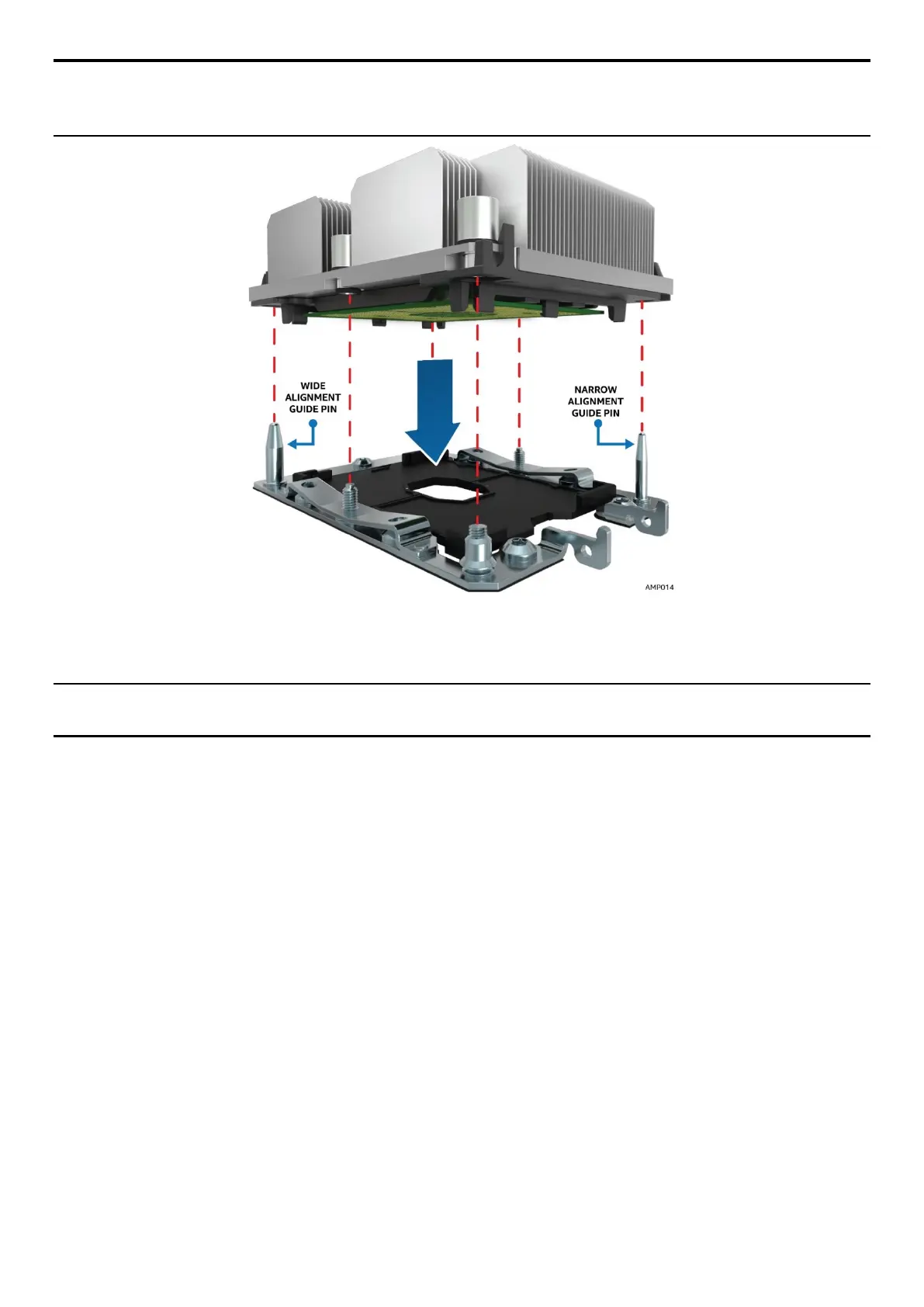
NOTE: Each of the two guide pins of the bolster plate has a different diameter. Each guide pin will have a
matching PHM mounting hole which allows for only one orientation when installed as shown in the
following figure. Look for the wide and narrow holes for proper and accurate alignment.
Figure 25. PHM Alignment to Bolster Plate
b. Lower the PHM onto the processor socket assembly.
CAUTION: Processor socket pins are delicate and bend easily. Use extreme care when placing the PHM
onto the processor socket.