2.6.2 Remove the CPU and Carrier Assembly
1. Power off the compute module and disconnect the power cable(s).
2. Remove the air duct. See section 2.3.1
.
3. Follow the procedures in Section 2.6.1 for LACC assembly removal
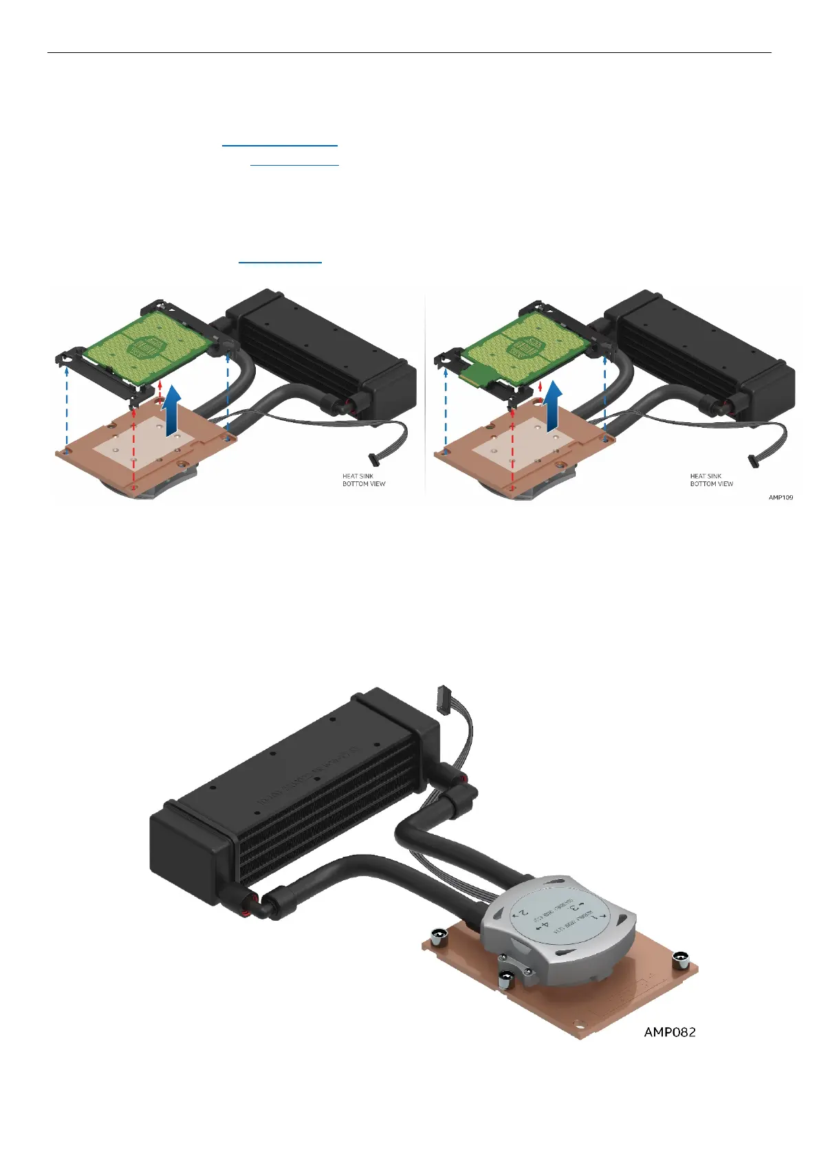
4. Turn the LACC and cold plate assembly over as shown in Figure 41
5. The LACC cold plate assembly is modeled after the passive air heatsink assembly. The sequence and
method of removing the CPU and Carrier is exactly the same as the passive air heatsink. This step is
only required if the CPU requires replacement. For simplification, refer to the CPU and Carrier
removal instructions in Section 2.5
for detail.
Figure 41. Releasing CPU and Carrier from Cold Plate
2.6.3 Install the 1U LACC Assembly
Figure 42. 1U LACC Assembly