Appendix B. POST Code Diagnostic LED Decoder
As an aid to assist in troubleshooting a system hang that occurs during a system’s Power-On Self-Test
(POST) process, the server board includes a bank of eight POST Code Diagnostic LEDs on the back edge of
the server board.
During the system boot process, Memory Reference Code (MRC) and System BIOS execute a number of
memory initialization and platform configuration processes, each of which is assigned a hex POST code
number. As each routine is started, the given POST code number is displayed to the POST Code Diagnostic
LEDs on the back edge of the server board.
During a POST system hang, the displayed post code can be used to identify the last POST routine that was
run prior to the error occurring, helping to isolate the possible cause of the hang condition.
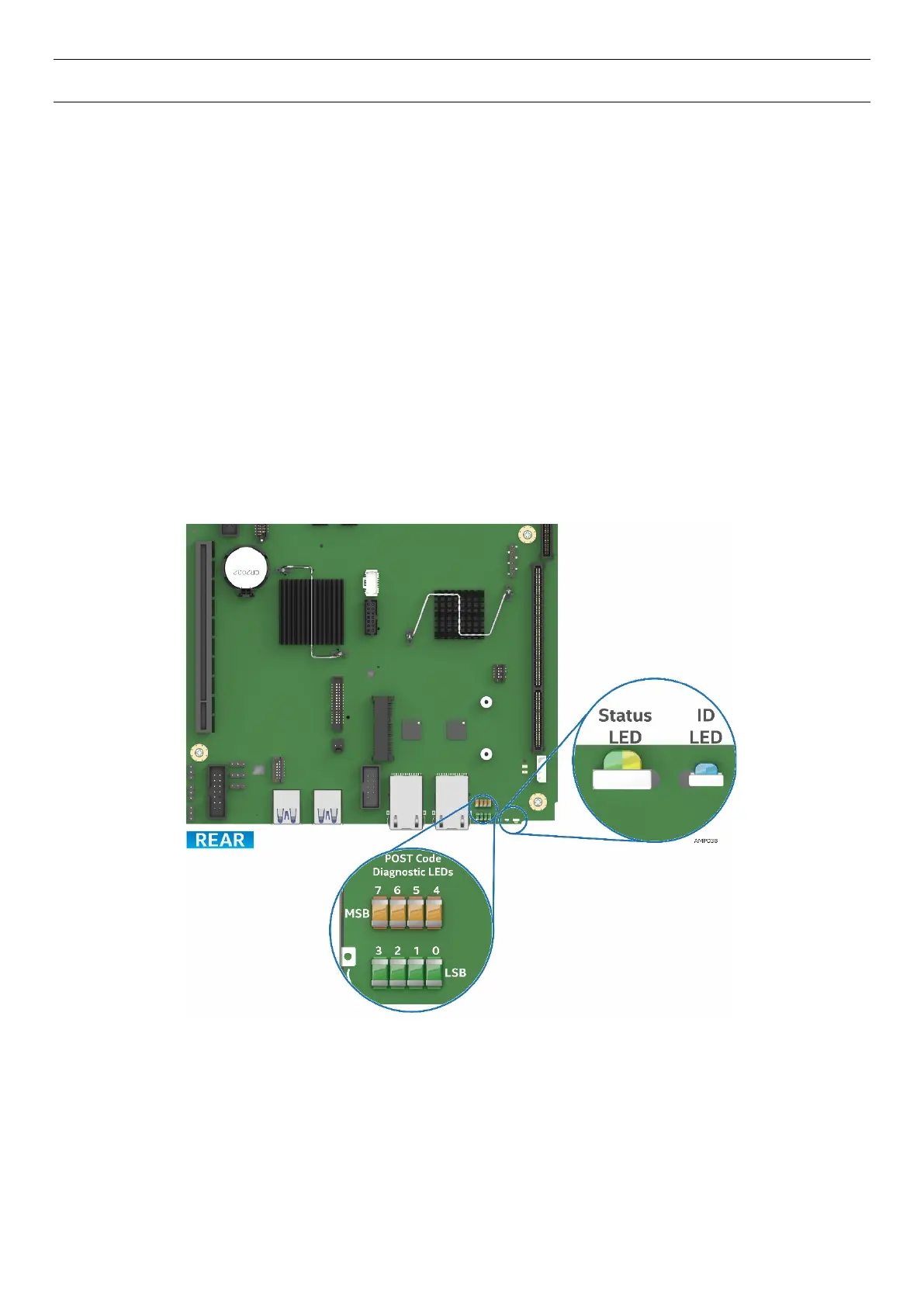
Each POST code is represented by eight LEDs; four Green and four Amber. The POST codes are divided into
two nibbles, an upper nibble and a lower nibble. The upper nibble bits are represented by Amber Diagnostic
LEDs #7, #6, #5, #4. The lower nibble bits are represented by Green Diagnostics LEDs #3, #2, #1 and #0. If
the bit is set in the upper and lower nibbles, the corresponding LED is lit. If the bit is clear, the corresponding
LED is off (Lit LED = 1, Off LED = 0).
Figure 91. POST Diagnostic LED Location