Goodrive300-01A-RT series integrated machine Wiring instruction
-12-
S1 S2 S3 PTC COM Y1 P1+
P1- PT1+ PT1-
+24V
GND
485+
485-
PT2+ PT2-
TA1 TC1 RO1A
V
P1
I
485Y1
COM
COM
+24V
J9
J3
J10 J1 J7
Simulation
interface
CN9
CN3
0V
AC220V
CN8
CN5
J4
Keypad
CN6
Keypad
CN2
Serial
download
RO1C
CN4
CN7
PW
COM
+24V
CME
GND
+24V
OUT
ON
J2
PE
GND
J6
J5
34PIN
CN1
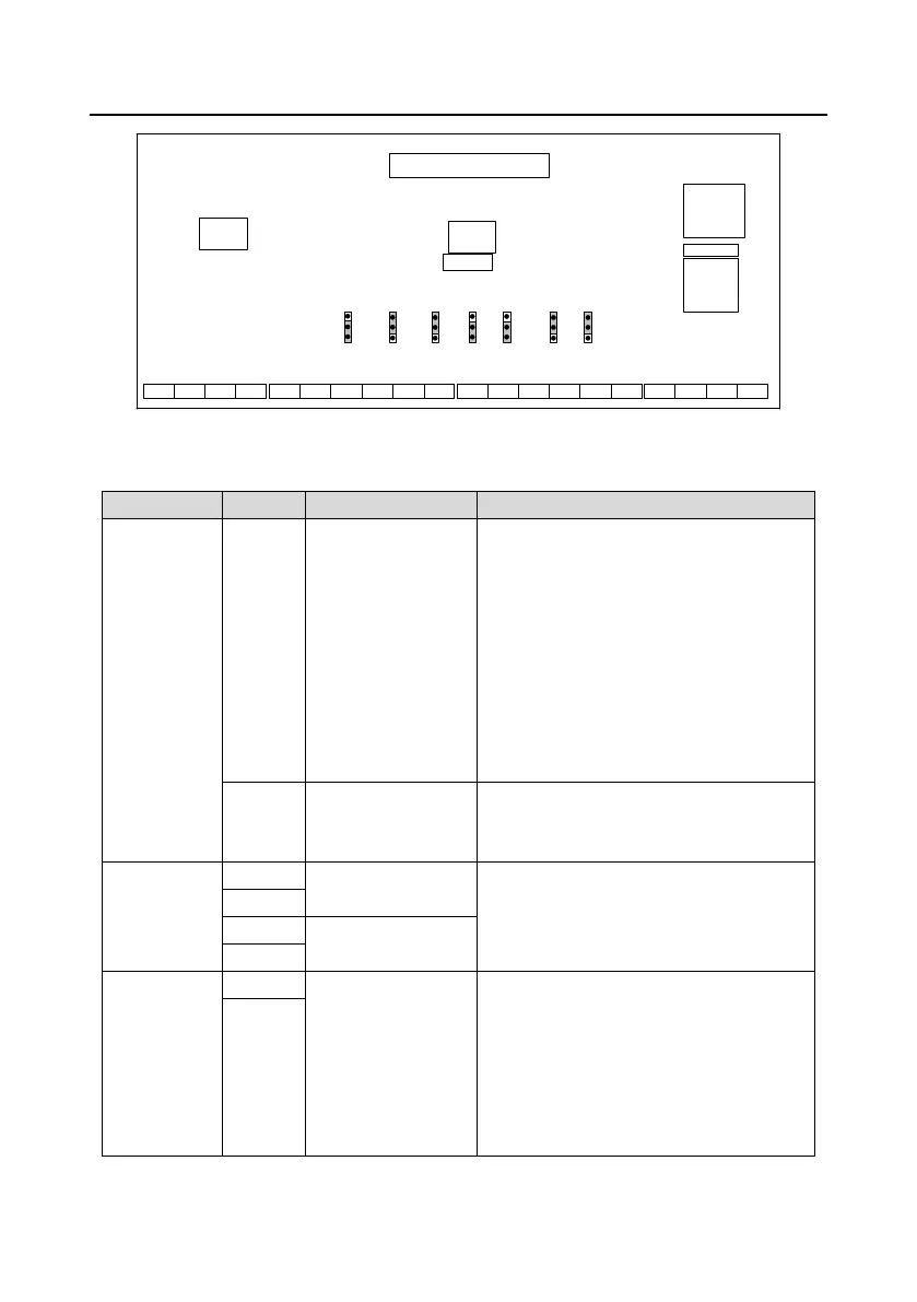
Figure 3-7 Control circuit terminal diagram
Table 3-3 User terminal description of control circuit
Provide 24V*(95%–110%) power to the
external, max. output current of 7.5kW VFD
models: 500mA, max. output current of other
VFD models: 1A.
Can be used to power up GPRS and touch
screen.
You can select +24V output or +24V and 1.1Ω
resistor series connection output through the
jumper J7. By default, +24V output is selected
in factory.
+24V and AO
reference ground
+24V reference ground
Short connecting GND to COM through the
jumper J10. Short connection is by default.
Analog temperature
signal 1
1. Resolution: 1°C
2. Range: -20°C–150°C
3. Detection precision: 3°C
Analog temperature
signal 2
1. Input range: current/voltage is optional,
4–20mA/2–10V corresponds to 0–1.6MPa; of
which P1 is switched via the jumper J1, and
the default is current type.
2. Input impedance: 20kΩ during voltage
input; 500Ω during current input
3. Resolution: 5mV (minimum value)
 Loading...


