Goodrive300-01A-RT series integrated machine Function description
-46-
groups) from the keypad to machine
Note: After the parameter is set to 1, 2, 3 or
4, and the operation is executed, the
parameter is automatically restored to 0.
0: No function
1: Jogging
2: Switch display status through the shifting
key
3: Forward/reverse running switching
4: Clear the setting of UP/DOWN
5: Coast to stop
6: Switch running-command giving methods
in sequence
7: Quick debugging mode (non-factory
parameter debugging)
Sequence of switching
running-command
channels by pressing
QUICK
0: Keypad→Terminal→Communication
1: Keypad←→Terminal
2: Keypad←→Communication
3: Terminal←→Communication
Stop function selection
of STOP/RST
0: Valid only for keypad control
1: Valid both for keypad and terminal control
2: Valid both for keypad and communication
control
3: Valid for all control modes
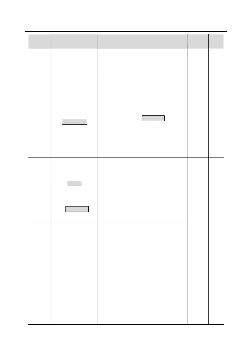
Selection 1 of
parameters displayed
in running state
0x0000–0xFFFF
BIT0: Running frequency (Hz on)
BIT1: Set frequency (Hz blinks)
BIT2: Bus voltage (V on)
BIT3: Output voltage (V on)
BIT4: Output current (A on)
BIT5: Running rotating speed (rpm on)
BIT6: Output power (% on)
BIT7: Output torque (% on)
BIT8: PID reference value (% blinks)
BIT9: PID feedback value (% on)
BIT10: Input terminal state
BIT11: Output terminal state
BIT12: Torque setting value (% on)
 Loading...


