Goodrive300-01A-RT series integrated machine Function description
-81-
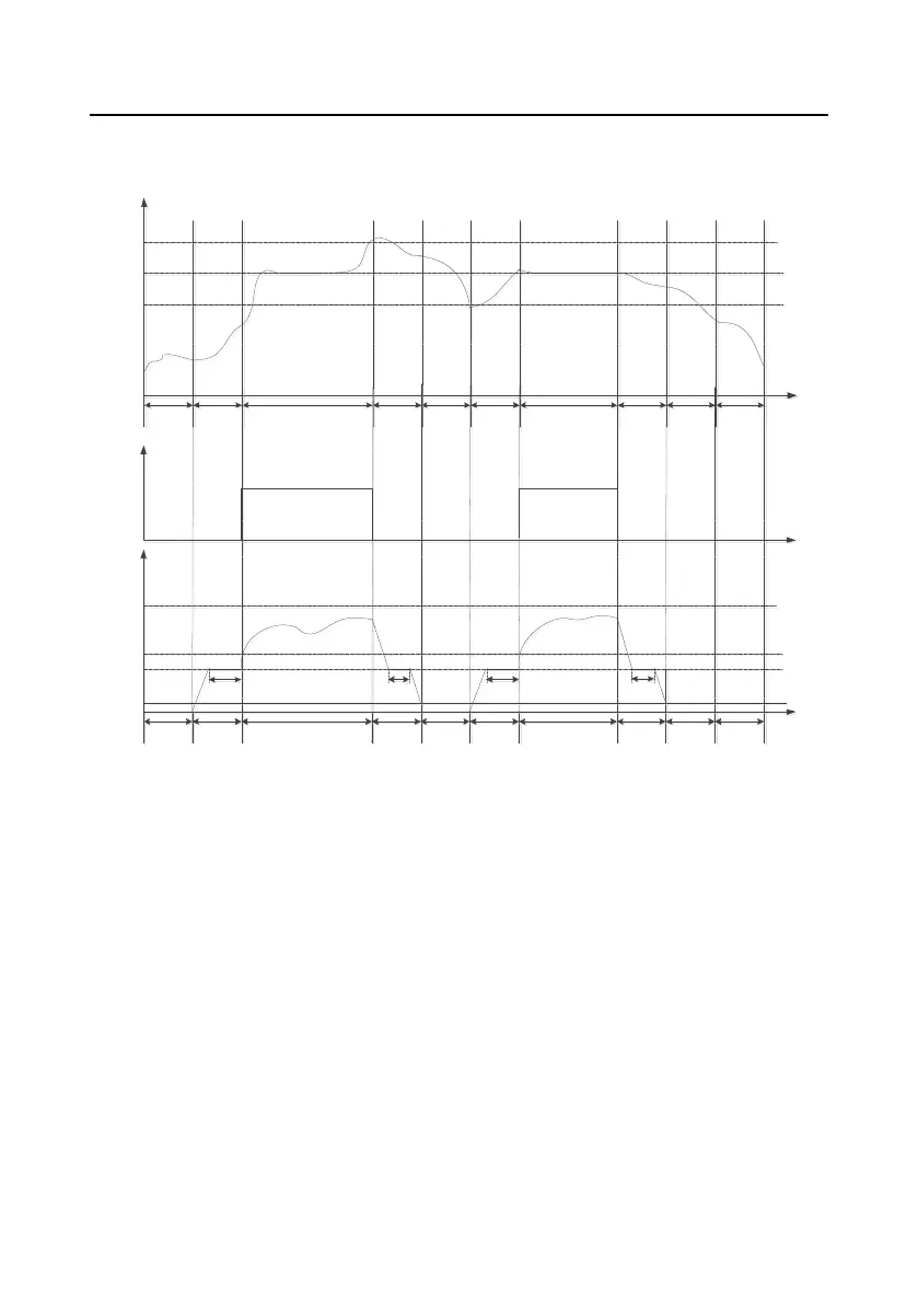
(2) The following figure shows the pressure & running frequency control during running of the air
compressor, and loading.
A B C D E F C G H A
Time
Present pressure
P18.05
P18.07
P18.06
0
A B C D E F C G H A
Time
Present running frequency
P00.04
P18.12
0
P18.11
P01.15
P18.15 P18.13 P18.15 P18.14
Loading valve
0
1
Figure 5-2 Air compressor pressure & running frequency control and loading
In above figure, P18.05 is unloading pressure; P18.06 is loading pressure; P18.07 is the set pressure.
P00.04 is upper limit frequency, P18.11 is lower limit value of load-carrying running frequency, P18.12
is no-load frequency, P01.15 is stop speed. Description of A-H stage control process is shown below:
A: Standby state
B: Starting stage of startup, duration is P18.15 (including part of the acceleration time P00.11);
C: Constant discharge stage of loading, pressure PID regulation is valid;
D: Unloading stage, duration includes part of deceleration time P00.12 and P18.13;
E: Sleep stage, the VFD does not run;
F: Starting stage of wake-up, duration is P18.15 (including part of the acceleration time P00.11);
G: Starting stage of stop, duration includes part of deceleration time P00.12 and P18.14;
H: Restart delay stage after stop, duration is P18.16.
 Loading...


