43
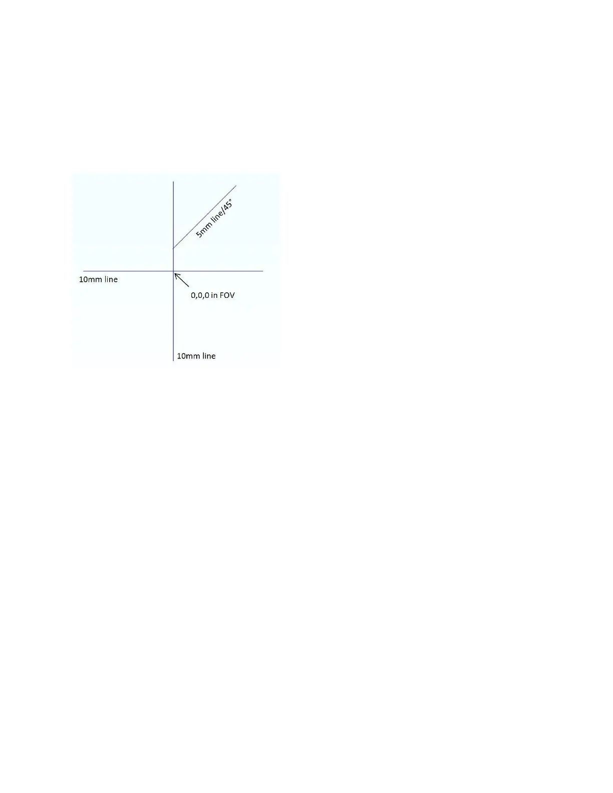
9. Using IPGScan software, mark a cross (as seen in Figure 5-9) at 0, 0, 0 in the scanners Field of
View (FOV). Once marked, make sure the head is not moved from this position until camera
setup is complete.
a. This cross will be used to determine camera orientation, set focus, and align cross-hairs.
b. Please refer to the IPGScan Manual (DOCOXUGGUIXX0001) for IPGScan operation.
Figure 5-9 IPGScan Camera Alignment Cross
10. Power on the camera using the supplied power cable.
a. Some Ethernet cameras utilize Power over Ethernet (POE).
11. Connect the camera to the proper interface.
a. HDMI Cameras will interface with a monitor/TV over an HDMI interface.
b. USB Cameras are made to interface with a computer, but do not interface with IPGScan
Software.
c. Ethernet Cameras interface with a computer and can be utilized inside of IPGScan
Software. Please refer to the IPGScan Manual (DOCOXUGGUIXX0001) for additional
setup information and features.
i. Ethernet cameras require a firmware version of 2.0201 installed.
12. Set the scanner so the mirrors are parked at 0, 0, 0 in the FOV using IPGScan software. The
following outlines a method of doing this but users can also refer to the IPGScan Manual
(DOCOXUGGUIXX0001).
a. Open the “Park At” window and ensure the prompt window is set to 0, 0, 0 and click
“Park” or click “Origin.” See Figure 5-10.