About the Product
Operator Station
Operator Station
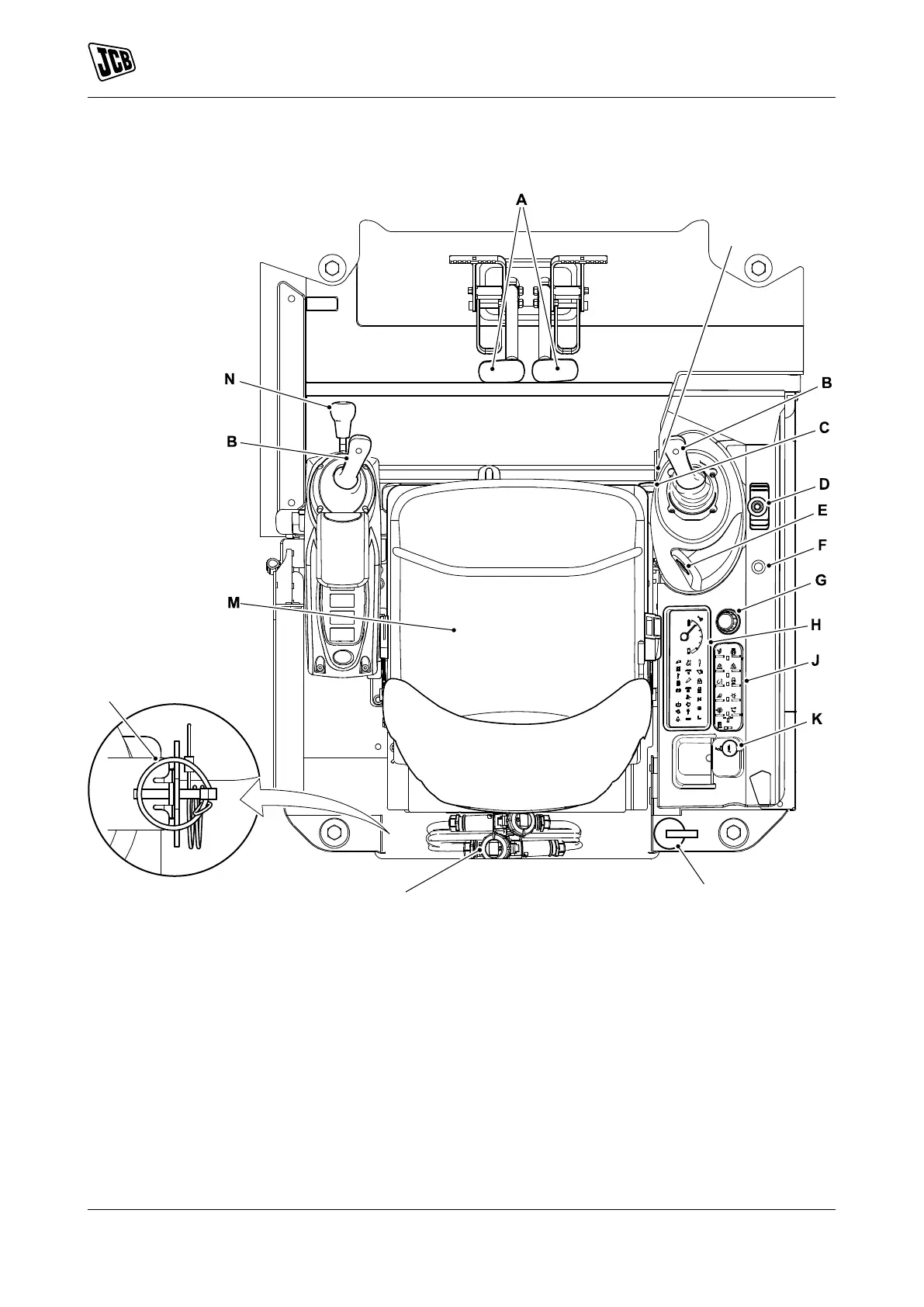
Component Locations
Figure 9.
A Track controls Refer to: Track Controls
(Page 45).
B Control lever Refer to: Excavator End Controls
(Page 53).
C Track extension lever Refer to: Retractable
Undercarriage Controls (Page 57).
D Dozer blade control lever/ 2-speed selection
button Refer to: Dozer Blade Controls
(Page 56).
E Ignition switch Refer to: Ignition Switch
(Page 17).
F Motor running indicator light
G Rotary hand throttle control Refer to: Hand
Throttle Control (Page 45).
H Instrument panel Refer to: Instrument Panel
(Page 47).
J Console switch panel Refer to: General
(Page 18).
K Auxiliary power socket Refer to: Auxiliary Power
Socket (Page 68).
L Fire extinguisher Refer to: Fire Extinguisher
(Page 69).
M Operator seat Refer to: Operator Seat
(Page 32).
N Control isolation lever Refer to: Control Lock
(Page 43).
P Charger cables
15 9831/8250-4 15
JCB © Admin Pimteam - 23/06/2021 05:32.