EasyManuals Logo

Johnson Controls York YCIV A Series User Manual

Johnson Controls York YCIV A Series
334 pages
To Next Page IconTo Next Page
To Previous Page IconTo Previous Page
Page #177 background imageLoading...
Page #177 background image
JOHNSON CONTROLS
177
SECTION 6 - TECHNICAL DATA
FORM 201.23-NM2
ISSUE DATE: 3/9/2015
6
COMPONENT LOCATIONS (CONT'D)
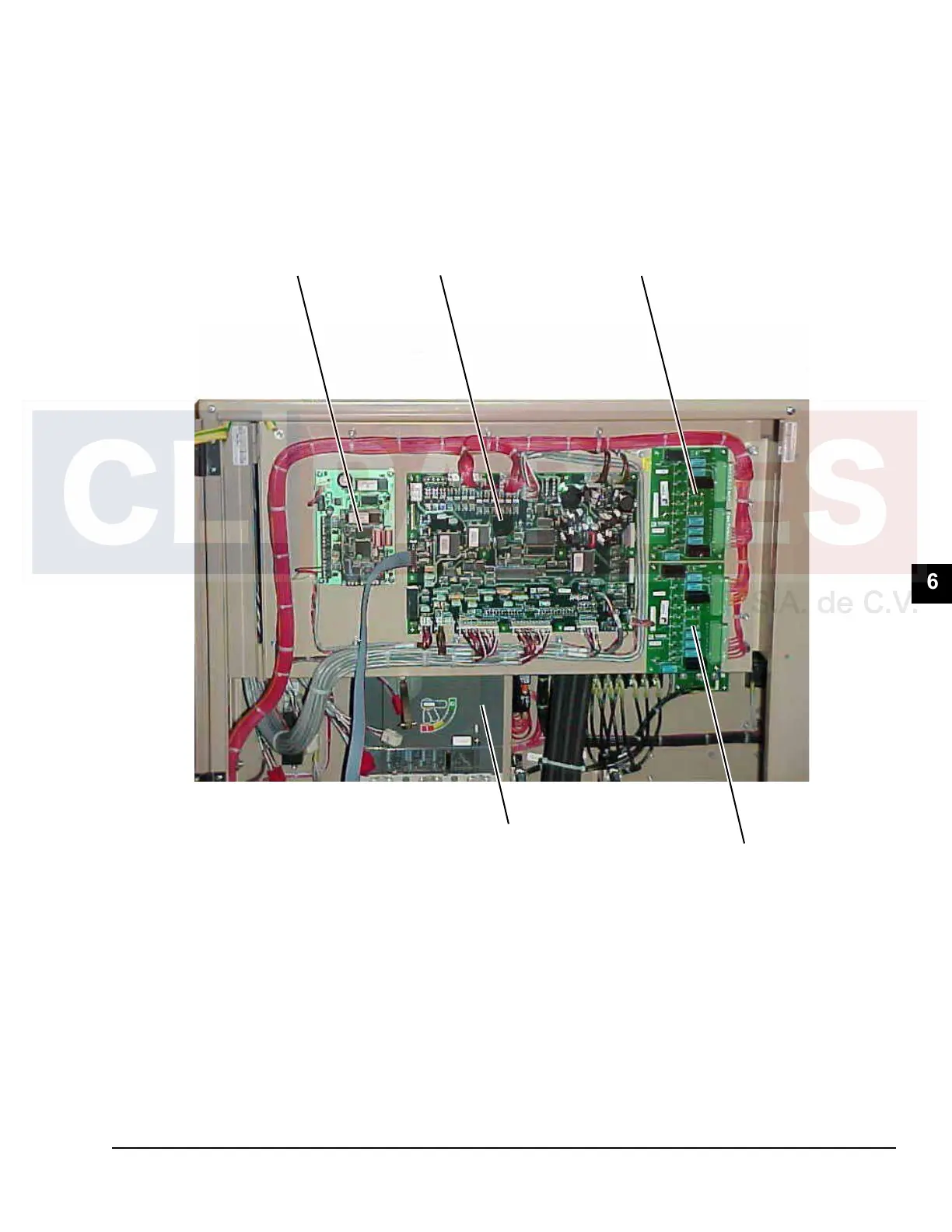
FIGURE 26 - CHILLER CONTROL BOARD, RELAY BOARDS, MICROGATEWAY, AND OPTIONAL CIRCUIT
BREAKER
LD10579
MICROGATEWAY
(OPTIONAL)
CHILLER
CONTROL
BOARD
RELAY BOARD #1
RELAY BOARD #2
OPTIONAL
CIRCUIT BREAKER
(Standard Unit will have terminal blocks.Input
power to the chiller will be connected here (see
Figures.-31 and 32)).

Table of Contents

Questions and Answers:

Question and Answer IconNeed help?

Do you have a question about the Johnson Controls York YCIV A Series and is the answer not in the manual?

Johnson Controls York YCIV A Series Specifications

General IconGeneral
BrandJohnson Controls
ModelYork YCIV A Series
CategoryChiller
LanguageEnglish

Related product manuals