JOHNSON CONTROLS
255
SECTION 8 - MICROPANEL
FORM 201.23-NM2
ISSUE DATE: 3/9/2015
8
The next key press indicates the % of compressor load-
ing and status of the economizer solenoid as deter-
mined by the operating frequency.
SYS 1 COMPRESSOR SPEED = XXX.X %
ECONOMIZER SOLENOID = XXX
XXX indicates whether the economizer solenoid is ei-
ther ON or OFF.
The next keypress displays the liquid level in the flash
tank and an indicator of the % the Flash Tank Feed
Valve is open.
SYS 1 FLASH TANK LEVEL = XXX.X %
FEED VALVE PERCENT OPEN = XXX.X %
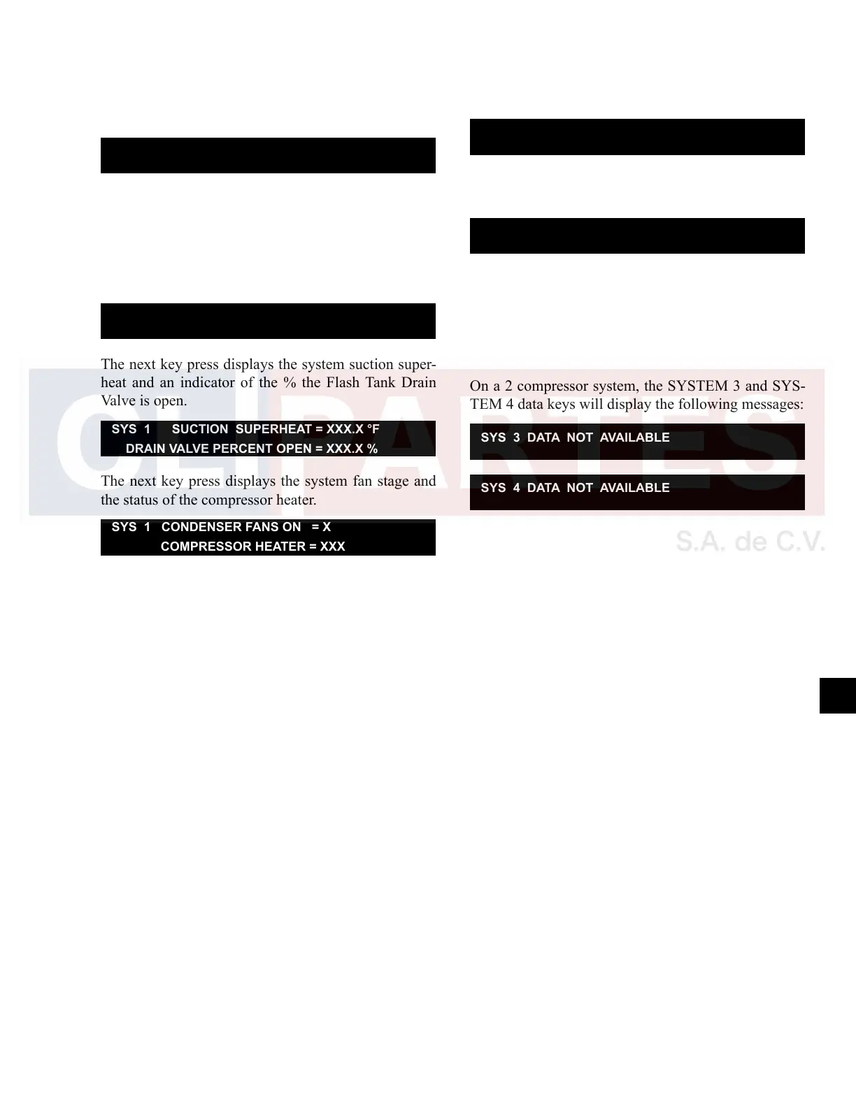
The next key press displays the system suction super-
heat and an indicator of the % the Flash Tank Drain
Valve is open.
SYS 1 SUCTION SUPERHEAT = XXX.X °F
DRAIN VALVE PERCENT OPEN = XXX.X %
The next key press displays the system fan stage and
the status of the compressor heater.
SYS 1 CONDENSER FANS ON = X
COMPRESSOR HEATER = XXX
X equals the number of fans ON. XXX indicates either
the heater is ON or OFF.
The next key press displays the system run time in
days, hours, minutes, and seconds.
SYS 1 RUN TIME
XX DAYS XX HOURS XX MINUTES XX SECONDS
The next key press displays the status of several system
signals.
SYS 1 RUN SIGNALS RELAY = XXX
RUN PERM = XXX SOFTWARE = XXX
XXX indicates either ON or OFF.
System 2 through 4 Data Key Operation
These keys function the same as the SYSTEM 1 DATA
key except that it displays data for System 2 through 4.
On a 2 compressor system, the SYSTEM 3 and SYS-
TEM 4 data keys will display the following messages:
SYS 3 DATA NOT AVAILABLE
SYS 4 DATA NOT AVAILABLE

 Loading...


