JOHNSON CONTROLS
254
FORM 201.23-NM2
ISSUE DATE: 3/9/2015
SECTION 8 - MICROPANEL
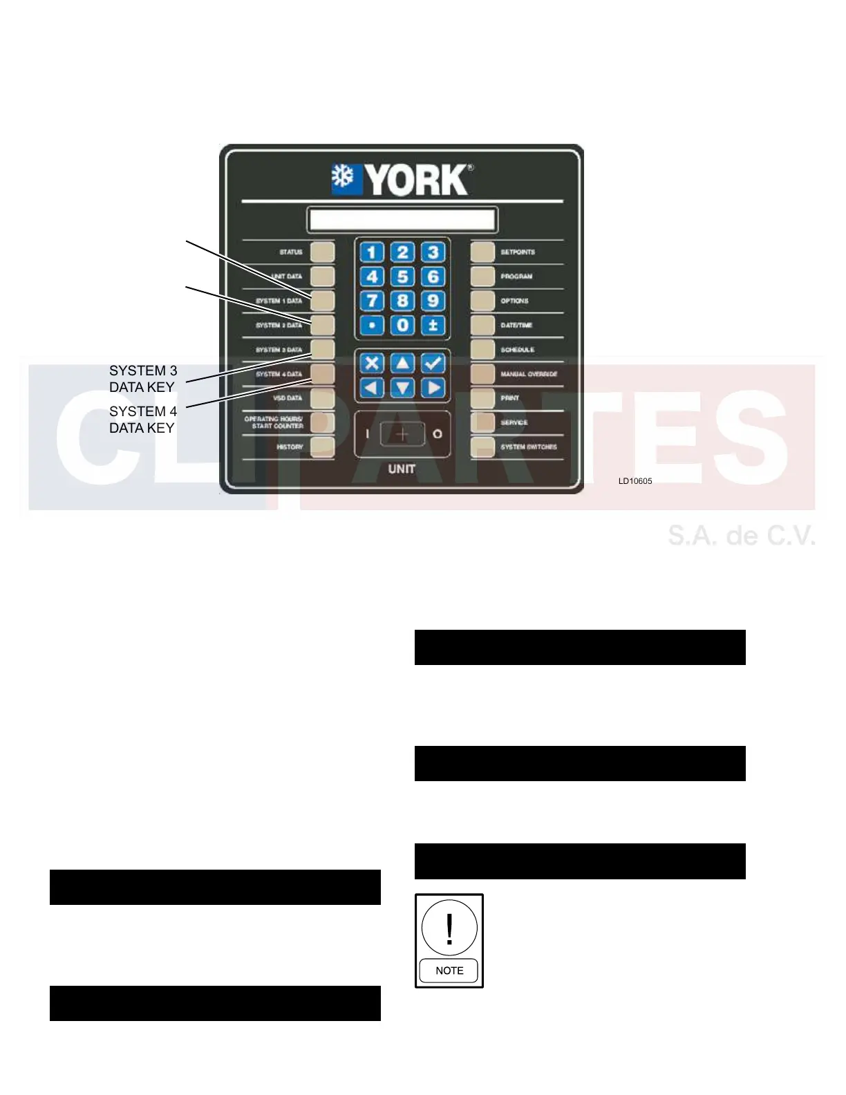
SYSTEM DATA KEYS 1 THROUGH 4
LD10605
SYSTEM 1
DATA KEY
SYSTEM 2
DATA KEY
SYSTEM 3
DATA KEY
SYSTEM 4
DATA KEY
General
The data keys provide the user with many displays of
individual system temperatures, pressures, and other
operating data. These keys have multiple displays,
which can be seen by repeatedly pressing the SYSTEM
DATAorthe▲or▼(ARROW) keys. An explanation
of each key and its messages is provided below.
System 1 Data Key Operation
The SYSTEM 1 DATA key provides the user with ac-
cess to System 1 operating parameters. The following
is a list of the data in the order in which it appears.
The first key press of the SYSTEM X DATA key dis-
plays all of the measured system pressures (oil, suc-
tion, and discharge).
SYS 1 PRESSURES OIL = XXXX PSIG
SUCTION = XXXX DISCHARGE = XXXX PSIG
The second key press of the SYSTEM DATA key or the
▼(DOWNARROW)keydisplaysallofthemeasured
system temperatures (oil, suction, and discharge).
SYS 1 TEMPERATURES OIL = XXX.X °F
SUCTION = XXX.X DISCHARGE = XXX.X °F
The next key press displays the suction temperature
and all of the calculated suction temperatures (satu-
rated suction and system superheat).
SYS 1 SUCTION TEMP = XXX.X °F
SUPERHEAT = XXX.X SAT TEMP = XXX.X °F
The next key press displays the discharge temperature
and all of the calculated discharge temperatures (satu-
rated discharge and discharge superheat).
SYS 1 DISCHARGE TEMP = XXX.X °F
SUPERHEAT = XXX.X SAT TEMP = XXX.X °F
The next key press displays the System 1 motor therm-
istor temperatures.
SYS 1 MOTOR TEMPS T1 = XXX.X °F
T2 = XXX.X °F T3 = XXX.X °F
If any motor temp sensor is being ignored,
(selectable under Unit Set-up Mode),
that sensor’s value will be displayed as
XXXXX.

 Loading...


