JOHNSON CONTROLS
256
FORM 201.23-NM2
ISSUE DATE: 3/9/2015
SECTION 8 - MICROPANEL
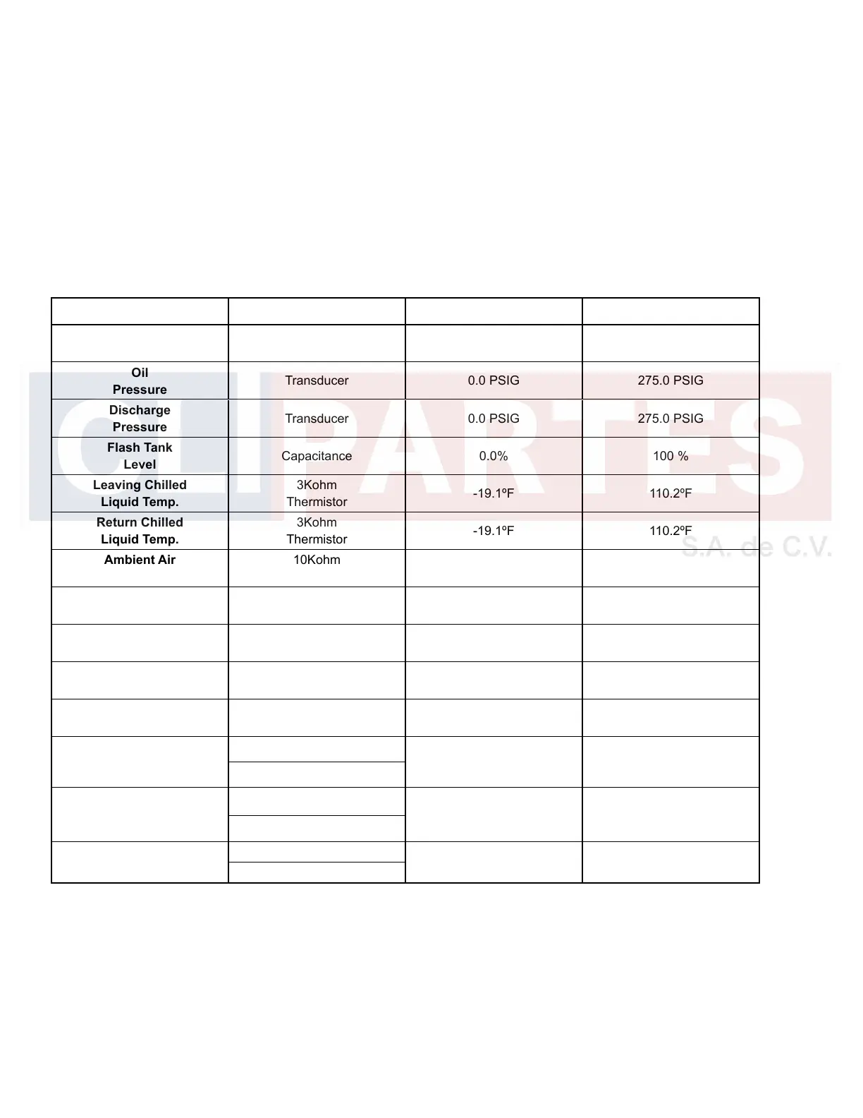
Sensor Displays
Table 15 on page 256 lists all the sensors attached
to the control board associated with system data keys.
The minimum and maximum values displayed on the
micro display are provided.
If values exceed the limits in the table, a < (less than)
or > (more than) sign will be display along with the
minimum or maximum value.
TABLE 15 - SENSOR MIN/MAX OUTPUTS
SENSOR TYPE MINIMUM MAXIMUM
Suction
Pressure
Transducer 0.0 PSIG 125.0 PSIG
Oil
Pressure
Transducer 0.0 PSIG 275.0 PSIG
Discharge
Pressure
Transducer 0.0 PSIG 275.0 PSIG
Flash Tank
Level
Capacitance 0.0% 100 %
Leaving Chilled
Liquid Temp.
3Kohm
Thermistor
-19.1ºF 110.2ºF
Return Chilled
Liquid Temp.
3Kohm
Thermistor
-19.1ºF 110.2ºF
Ambient Air
Temp.
10Kohm
Thermistor
-4.6ºF 137.9ºF
Suction
Temp.
3Kohm
Thermistor
-4.1ºF 132.8ºF
Oil Temp.
50Kohm
Thermistor
40.3ºF 302.6ºF
Discharge
Temp.
50Kohm
Thermistor
40.3ºF 302.6ºF
Compressor
Motor Temp.
10Kohm
Thermistor
-30.0ºF 302.0ºF
Remote Temp.
Reset
4-20mA/2-10VDC
0 % 100 %
0-20mA/0-10VDC
Remote
Current Limit
4-20mA/2-10VDC
0 % 100 %
0-20mA/0-10VDC
Remote
Sound Limit
4-20mA/2-10VDC
0 % 100 %
0-20mA/0-10VDC

 Loading...


