JOHNSON CONTROLS
294
FORM 201.23-NM2
ISSUE DATE: 3/9/2015
SECTION 8 - MICROPANEL
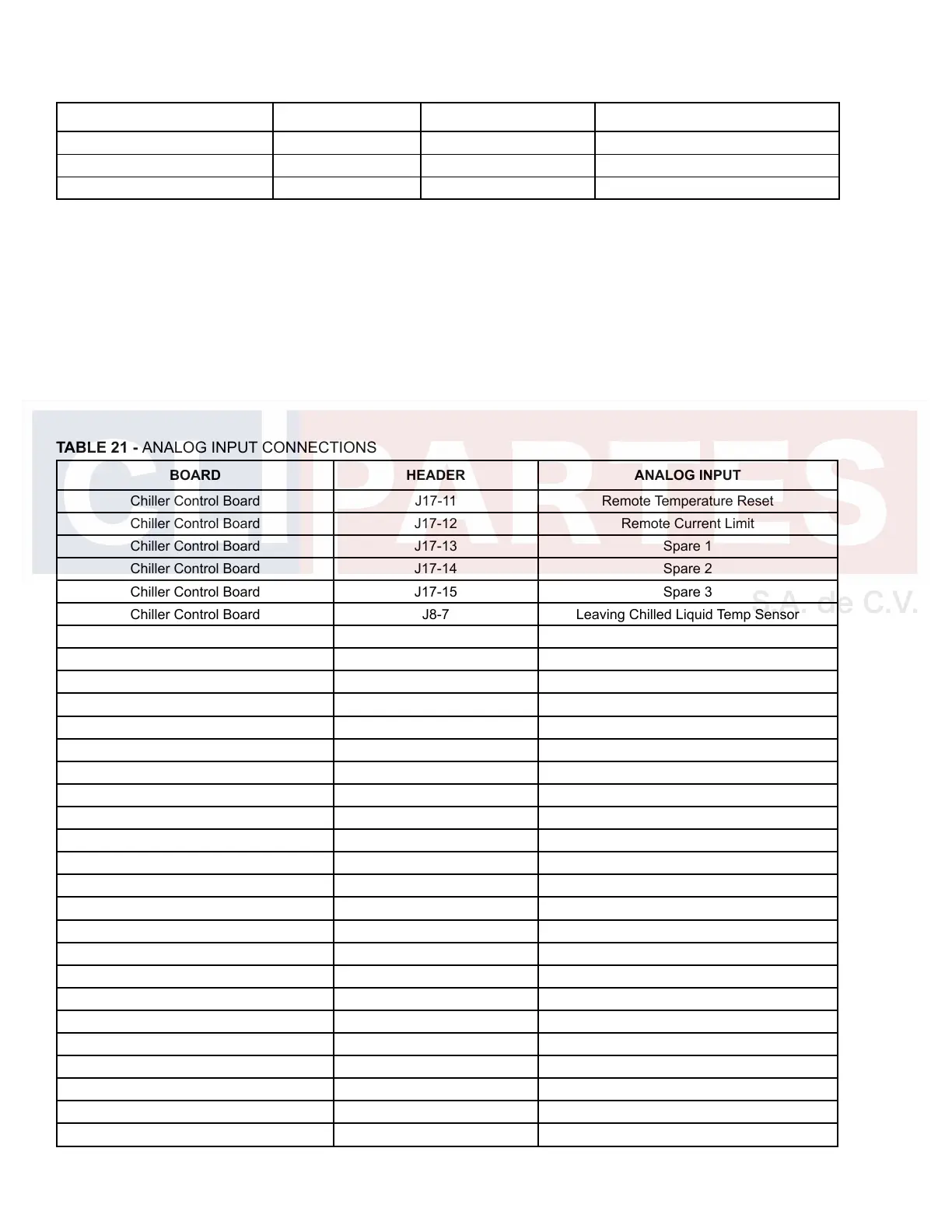
TABLE 21 - ANALOG INPUT CONNECTIONS
BOARD HEADER ANALOG INPUT
Chiller Control Board J17-11 Remote Temperature Reset
Chiller Control Board J17-12 Remote Current Limit
Chiller Control Board J17-13 Spare 1
Chiller Control Board J17-14 Spare 2
Chiller Control Board J17-15 Spare 3
Chiller Control Board J8-7 Leaving Chilled Liquid Temp Sensor
Chiller Control Board J8-8 Return Chilled Liquid Temp Sensor
Chiller Control Board J8-9 Ambient Air Temp Sensor
Chiller Control Board J19-1 Comp 1 Motor Temperature 1
Chiller Control Board J19-2 Comp 1 Motor Temperature 2
Chiller Control Board J19-3 Comp 1 Motor Temperature 3
Chiller Control Board J19-6 Comp 2 Motor Temperature 1
Chiller Control Board J19-7 Comp 2 Motor Temperature 2
Chiller Control Board J19-8 Comp 2 Motor Temperature 3
Chiller Control Board J21-13 Sys 1 Suction Temperature
Chiller Control Board J21-3 Sys 1 Oil Temperature
Chiller Control Board J21-16 Sys 1 Discharge Temperature
Chiller Control Board J21-6 Sys 1 Flash Tank Level Sensor
Chiller Control Board J21-20 Sys 1 Suction Pressure
Chiller Control Board J21-22 Sys 1 Oil Pressure
Chiller Control Board J21-24 Sys 1 Discharge Pressure
Chiller Control Board J22-13 Sys 2 Suction Temperature
Chiller Control Board J22-2 Sys 2 Oil Temperature
Chiller Control Board J22-16 Sys 2 Discharge Temperature
Chiller Control Board J22-6 Sys 2 Flash Tank Level Sensor
Chiller Control Board J22-20 Sys 2 Suction Pressure
Chiller Control Board J22-22 Sys 2 Oil Pressure
Chiller Control Board J22-24 Sys 2 Discharge Pressure
Chiller Control Board J20-1 Comp 3 Motor Temperature 1
TABLE 20 - SERIAL PORT CONNECTIONS
BOARD HEADER PORT TYPE PORT USE
Chiller Control Board TB1 / TB2 RS-232 / RS-485 Printer/RCC and ISN
Chiller Control Board J2 / J1 RS-485 Control Panel <-> VSD #1 / #2
VSD Logic Board J12 Opto- Coupled RS-485 VSD <-> Control Panel
ANALOG INPUT CONNECTIONS
Table 21 on page 294 lists the Analog inputs and the
circuit board they are located on. Not all of the sen-
sors are installed in every unit, as some of them are
optional. The software must read the optional sensors
if installed. The Analog input signals are typically ref-
erenced to the common (return, ground) in the system.
J12-3 can also be used as common, as well as chassis
ground, or the common terminal point on the Chiller
Control Board. See the wiring diagrams. The +DC
Bus, -DC Bus and ½ DC Bus voltages are measured
in reference to one of the other DC Bus points. For
example: +DC Bus measured to ½ DC Bus.

 Loading...


