JOHNSON CONTROLS
203
SECTION 6 - TECHNICAL DATA
FORM 201.23-NM2
ISSUE DATE: 3/9/2015
6
The capacitor bank in conjunction with the 1L Line
Inductor forms a low pass LC Filter and provides fur-
ther smoothing (filters ripple) to the rectified DC.
Equalizing/Bleeder resistors connected across the
banks equalize the voltage between the top and bottom
capacitors to avoid damaging the capacitors from over
voltage. The Equalizing/Bleeder resistors also provide
a path for discharge of the capacitors when the drive is
switched off. This safely discharges the capacitors in
approximately 5 minutes. Always be careful, a bleeder
resistor could be open and the bus may be charged.
LD10611
EQUALIZING/BLEEDER
RESISTORS
When servicing, always check the
DC Bus Voltage across the top and
bottom, banks of capacitors with a
known functioning voltmeter
correctly set to the proper scale before
performing service on the inverter. DO
NOT rely on the Bleeder Resistors to
discharge the capacitor banks without
checking for the purpose of safety.
NEVER short out a capacitor bank to
discharge it during servicing. If a bleeder
resistor is open and a capacitor bank will
not discharge, immediately contact John-
son Controls Product Technical Support.
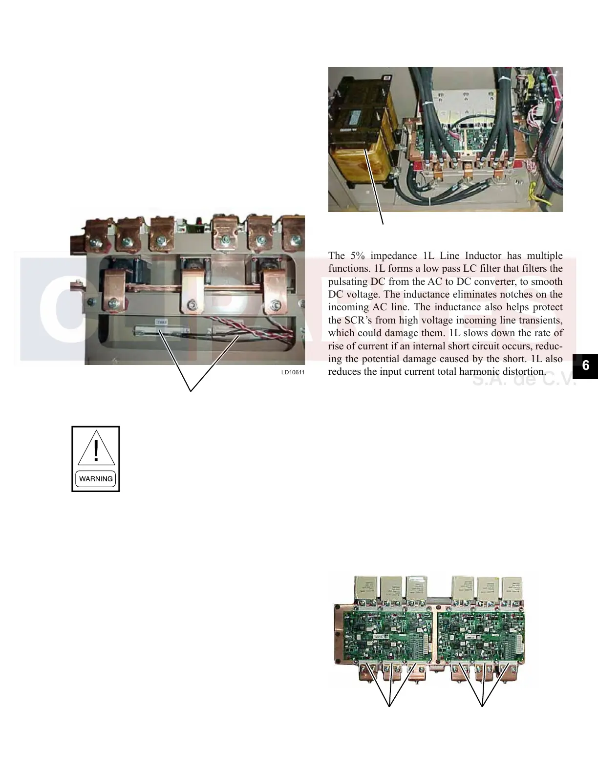
1L Line Inductor
LD10612
1L LINE INDUCTOR
The 5% impedance 1L Line Inductor has multiple
functions. 1L forms a low pass LC filter that filters the
pulsating DC from the AC to DC converter, to smooth
DC voltage. The inductance eliminates notches on the
incoming AC line. The inductance also helps protect
the SCR’s from high voltage incoming line transients,
which could damage them. 1L slows down the rate of
rise of current if an internal short circuit occurs, reduc-
ing the potential damage caused by the short. 1L also
reduces the input current total harmonic distortion.
DC to AC Inverter
The DC to AC Inverter section converts the rectified
and filtered DC back to AC at the equivalent magni-
tude and frequency to run a compressor at a specific
speed. Although a common DC Bus links the compres-
sor drive outputs, each compressor has its own inverter
output module. Each inverter output module consists
of 6 IGBT’s (3 modules) and an IGBT Gate Driver
Board, which converts DC to a 3 - phase AC output.
The IGBT’s are mounted to the liquid cooled heatsink
designed to take the heat away from the devices and re-
move it in the condenser. The IGBT Gate Driver Board
provides gating pulses to turn the IGBT’s ON and OFF.
LD10613
IGBT's IGBT's

 Loading...


