EasyManuals Logo

Johnson Controls York YCIV A Series User Manual

Johnson Controls York YCIV A Series
334 pages
To Next Page IconTo Next Page
To Previous Page IconTo Previous Page
Page #191 background imageLoading...
Page #191 background image
JOHNSON CONTROLS
191
SECTION 6 - TECHNICAL DATA
FORM 201.23-NM2
ISSUE DATE: 3/9/2015
6
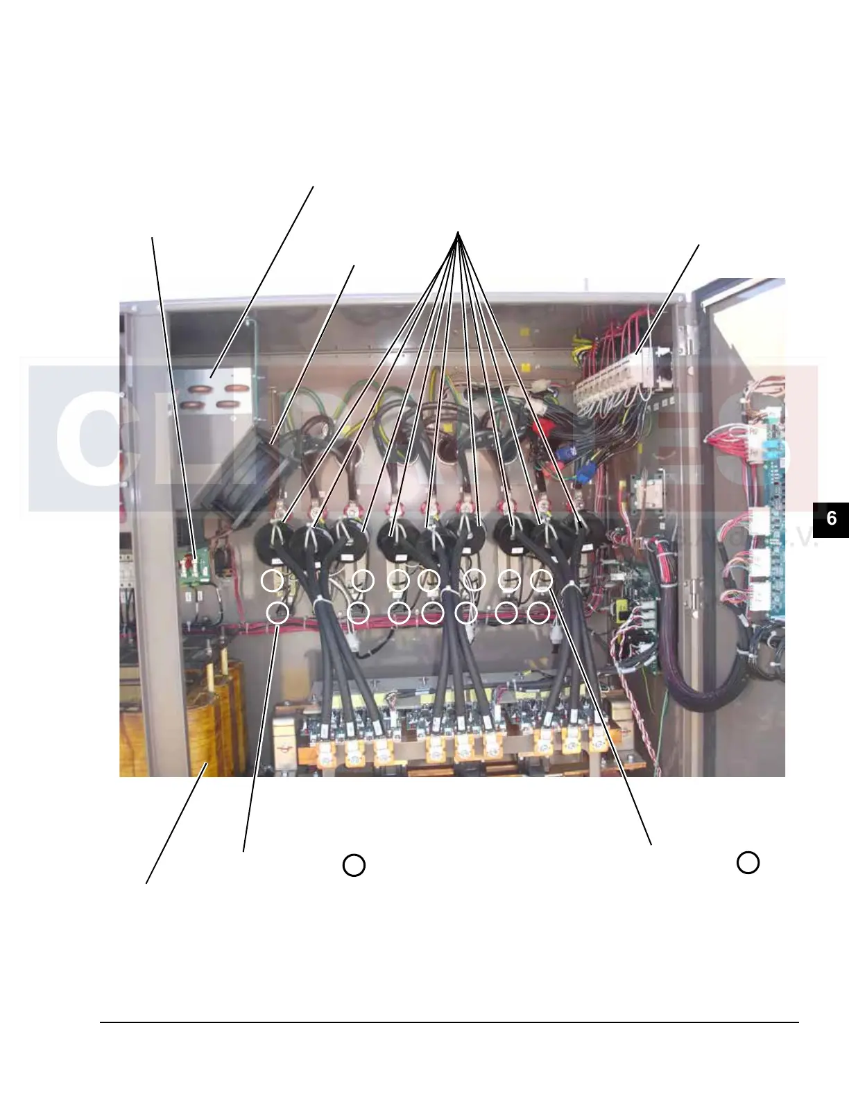
FIGURE 40 - VSD COMPONENTS, 3 COMPRESSOR
50073
FAN
RELAYS
CURRENT
TRANSFORMERS
(C14, C13, 12, 9, 8, 7, 6, 5, 4)
COOLING
FAN
LINE
INDUCTORS
CABINET
COOLING
COIL
TRANSIENT
SUPPRESSOR
BOARD
W/ 11FU, 12FU,
AND 13 FU FUSES
(3 Phase Input)
1 1 1 1 1 1 1
2
2 2 2 2 22
SNUBBER CAPS
c24, 25, 26, 21
22, 23, 18, 19, 20
SNUBBER RESISTORS
res15, 16, 17, 18, 19, 20,
9, 10, 11, 12, 13, 14, 3, 4,
5, 6, 7, 8
1
2
COMPONENT LOCATIONS (CONT'D)

Table of Contents

Questions and Answers:

Question and Answer IconNeed help?

Do you have a question about the Johnson Controls York YCIV A Series and is the answer not in the manual?

Johnson Controls York YCIV A Series Specifications

General IconGeneral
BrandJohnson Controls
ModelYork YCIV A Series
CategoryChiller
LanguageEnglish

Related product manuals