JOHNSON CONTROLS
288
FORM 201.23-NM2
ISSUE DATE: 3/9/2015
SECTION 8 - MICROPANEL
SERVICE AO J14-1 SYS 3 FEED VALVE OUT
XXX.X % = XX.X VDC
SERVICE AO J14-2 SYS 3 DRAIN VALVE OUT
XXX.X % = XX.X VDC
SERVICE AO J14-3 SYS 4 FEED VALVE OUT
XXX.X % = XX.X VDC
SERVICE AO J14-4 SYS 4 DRAIN VALVE OUT
XXX.X % = XX.X VDC
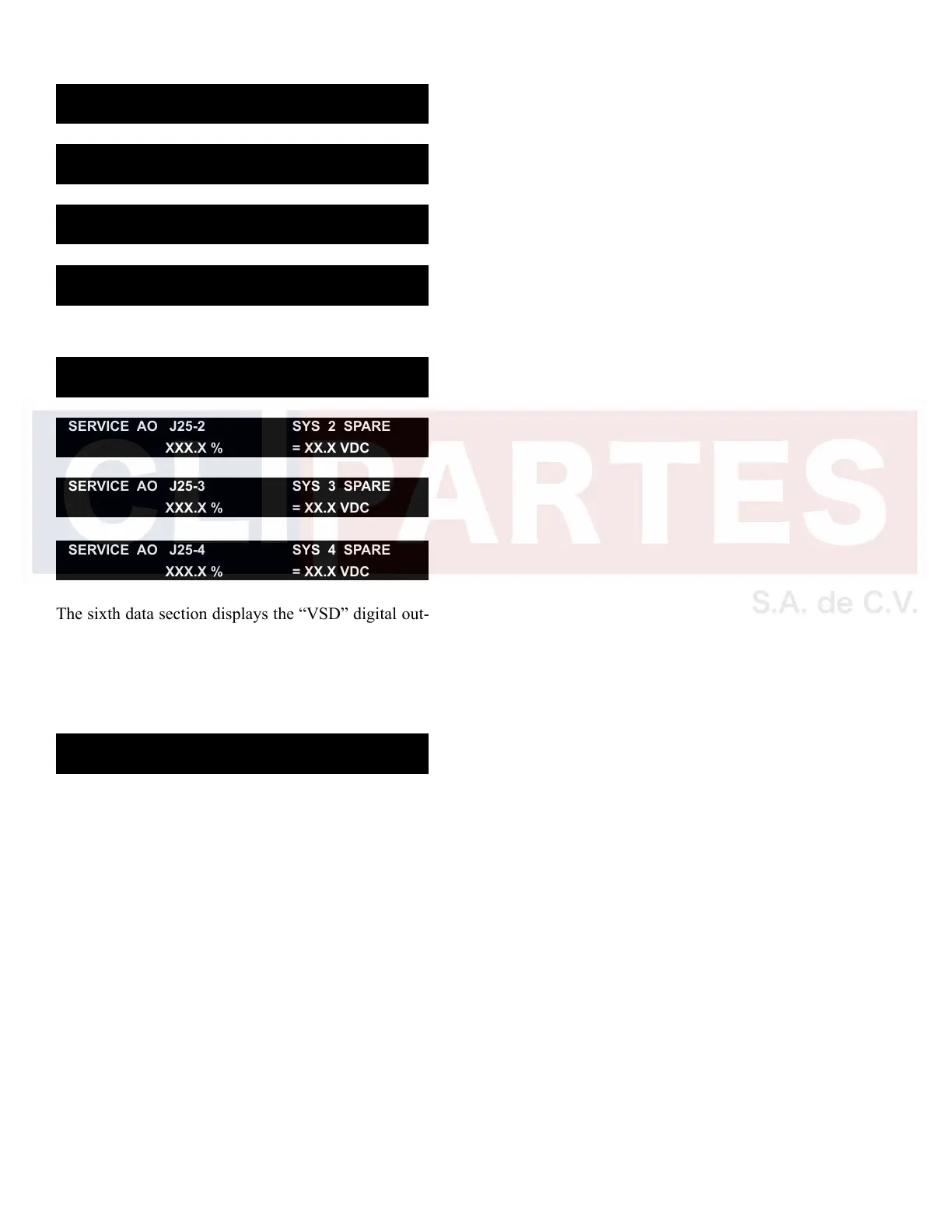
SERVICE AO J25-1 SYS 1 SPARE
XXX.X % = XX.X VDC
SERVICE AO J25-2 SYS 2 SPARE
XXX.X % = XX.X VDC
SERVICE AO J25-3 SYS 3 SPARE
XXX.X % = XX.X VDC
SERVICE AO J25-4 SYS 4 SPARE
XXX.X % = XX.X VDC
The sixth data section displays the “VSD” digital out-
puts (DO) that can be viewed from the Service Mode.
The Digital Output signals indicate the status of the
output. The 0 to 120VAC digital outputs are referenced
to neutral (Wire 2).
SERVICE DO J10-2 VSD COOLING FAN/PUMP
VSD LOGIC STATUS = XXX

 Loading...


