Do you have a question about the JRC RADAR 1800 and is the answer not in the manual?
Details the meaning of various warning and cautionary symbols.
Describes the warning label found on the unit.
Highlights critical safety warnings related to unit operation.
Crucial note regarding equipment performance and installation.
Key considerations and suggestions for installing the equipment.
Information on suppression ferrites used for EMC.
Illustrates the external view of the scanner unit.
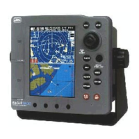
Shows the external view of the display unit.
Depicts the external view of the optional GPS/DGPS sensors.
Explains the primary purpose and capabilities of the radar system.
Highlights the key operational and technological features of the unit.
Lists and describes the standard and optional components of the system.
Details the items included in the standard package.
Describes the optional GPS/DGPS sensors available.
Provides dimensional information and physical layout of the units.
Illustrates how the main components of the system are connected.
Steps for installing the main display unit.
Factors to consider when selecting a mounting location.
Describes the standard method for mounting the unit using its yoke.
Instructions for flush or surface mounting the display unit.
Procedures for mounting and connecting the scanner unit.
Details on connecting the scanner unit's cable.
Steps for installing the GPS/DGPS sensor.
Guidance on choosing an optimal location for the sensor.
General steps to follow during the installation process.
Instructions for connecting the unit to the vessel's DC power supply.
Importance and method of properly grounding the display unit.
How to connect external navigation sensors and data.
Connecting optional compass units for heading information.
Steps for initial power-on and system configuration.
Checks to perform after installation before energizing the unit.
Guide to using the installation menu for system settings.
Procedures for optimizing radar performance through adjustments.
Adjusting receiver tuning for optimal signal reception.
Calibrating bearing readings for accurate picture orientation.
Adjusting display timing for correct target distance measurement.
Setting the sensitivity for suppressing sea clutter.
How to connect the unit to a PC for data transfer.
Instructions for inserting a C-MAP chart card.
Steps for safely removing a chart card.
Overview of the radar display screen elements and their functions.
Identifies and explains the function of each button on the control panel.
Details the connectors and ports located on the rear of the unit.
Fundamental operations for powering on and initial system display.
Instructions for powering the unit on, off, and into standby mode.
How to adjust display brightness and contrast.
Switching between different display configurations like RADAR, CHART, etc.
Viewing the radar display in full screen.
Displaying radar and chart data simultaneously.
Viewing the chart display in full screen.
Displaying navigation data, course, and heading information.
Showing navigation information in a numerical data format.
Accessing details about the vessel's status and waypoints.
How to use the jog dial for menu navigation and control adjustments.
How to use the joystick for cursor control and menu selection.
Basic steps for navigating and operating through the unit's menus.
Adjusting the radar's display range scale.
Fine-tuning the receiver gain for optimal target detection.
Manual adjustment of the radar's tuning for signal clarity.
Controls to minimize interference from sea reflections.
Controls to minimize interference from rain or snow.
Adjusting the display picture's position.
Methods for measuring distances to targets on the radar.
Techniques for measuring the bearing to targets.
Turning radar range rings on or off.
Selecting the radar bearing display mode.
Main menu for configuring various radar parameters.
Operating the chart plotter functions using the joystick.
Marking an event symbol on the chart.
Adding waypoints or marks to the chart.
Adding a new waypoint to the system.
Procedures for saving waypoint data.
Function to mark the vessel's position in case of man overboard.
Adjusting the range scale in different chart display modes.
Configuring navigation parameters and selecting routes.
Choosing a route for navigation.
Navigating directly to a selected waypoint.
Following a pre-defined route.
Creating and navigating a temporary route.
Finding and navigating to the nearest port.
Returning to a previous Man Overboard position.
Setting the order for waypoint navigation.
Choosing how to advance between waypoints.
Viewing tide height graphs for specific locations.
Accessing detailed information about points of interest.
Functions for modifying, erasing, and managing waypoints and routes.
Options for editing existing waypoints.
Editing waypoints directly on the chart display.
Common operations for managing waypoints.
Editing waypoints through a list view.
Duplicating existing waypoint data.
Removing waypoints from the system.
Navigating through waypoint list pages.
Creating new navigation routes.
Procedures for saving a new route.
Modifying existing routes.
Inserting waypoints into routes.
Editing waypoints within routes.
Deleting waypoints from routes.
Clearing all stored route and waypoint data.
Converting recorded tracks into navigation routes.
Choosing points from a track to define a new route.
Dividing tracks or routes based on conditions.
Drawing lines and rectangles on the chart.
Methods for constructing graphical elements on the chart.
Steps to draw a line on the chart.
Steps to draw a rectangle on the chart.
Basic principles of menu navigation and interaction.
Accessing the main menu structure of the unit.
Main menu for configuring various radar parameters.
Selecting the radar bearing display mode.
Common maintenance tasks applicable to all unit components.
Procedures for cleaning the unit's exterior.
Checking for loose connections of assembly screws.
Verifying the integrity of cable connections.
Maintenance procedures specific to the scanner unit.
Maintenance for the radome and its internal gears.
Cleaning the radome surface for optimal radar performance.
Instructions for lubricating internal gears.
Maintenance for the display unit screen.
How to clean the LCD screen without damage.
Fundamental concepts and operation of radar systems.
Factors affecting the strength of radar target echoes.
Explanation of noise caused by rough seas on the radar display.
Types of false echoes that can appear on the radar screen.
Radar signal blockage due to surrounding structures.
Weak radar signals from side lobes causing false targets.
False echoes caused by reflections from the ship's structure.
False echoes from reflections between large objects.
Interference patterns caused by other radars.
Introduction to Global Positioning System and Differential GPS.
Explanation of how the GPS system works.
How Differential GPS improves accuracy.
Explanation of the WAAS system for GPS accuracy enhancement.
Overview of the interswitch device and its purpose.
List of parts included with the interswitch unit.
Diagram illustrating the physical layout of the interswitch system.
Instructions for installing the interswitch unit and setting jumpers.
Configuration of jumpers for interswitch operation modes.
Wiring instructions for connecting the display units and other components.
Explains the operation modes based on jumper settings.
Configuration of the BZ alarm for scanner rotation errors.
Guidance on contacting support for operational issues.
Terms and conditions for warranty repairs.
Information on paid repair services after the warranty expires.
Information required when requesting service.
Recommendations for periodic checks and inspections.
Safety precautions for disposing of the LCD module.
Compliance with regulations for disposing of the entire unit.
Safety measures for handling and disposing of lithium batteries.
General specifications applicable to the entire system.
Technical specifications for the radar scanner unit.
Technical specifications for the display unit.
Technical specifications related to the radar functionality.
Technical specifications for the chart plotter functionality.
Details on the input and output signal interfaces.
Electrical schematic showing component connections.
Table listing available geodetic systems for position referencing.
Information on NMEA0183 data formats used for communication.
List of NMEA0183 sentences the unit can receive.
List of NMEA0183 sentences the unit can transmit.
A template for recording waypoint information.
| Brand | JRC |
|---|---|
| Model | RADAR 1800 |
| Category | Marine Radar |
| Language | English |