•
DC power supply—Switch the circuit breaker on the panel board that services the
DC circuit to the off position.
4. Remove the power source cable from the power supply faceplate:
•
AC power supply—Remove the power cord from the power supply faceplate by
detaching the power cord retainer and gently pulling out the female end of the
power cord connected to the power supply faceplate.
•
DC power supply—Remove the screws securing the ring lugs attached to the power
source cables to the power supply using the screwdriver, and remove the power
source cables from the power supply. Replace the screws on the terminals and
tighten them.
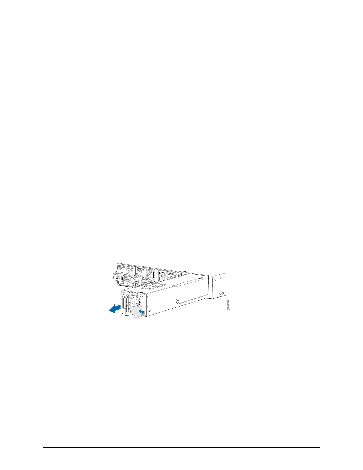
5. Slide the locking lever toward the handle until it stops.
6. Grasp the power supply handle and pull firmly to slide the power supply halfway out
of the chassis.
7. Place one hand under the power supply to support it and slide it completely out of
the chassis. Take care not to touch power supply components, pins, leads, or solder
connections.
8. Place the power supply in the antistatic bag or on the antistatic mat placed on a flat,
stable surface.
Figure 37: Removing a Power Supply from a QFX5110
Installing a Power Supply in a QFX5110
All QFX5110 switches, except the QFX5110-32Q-CHAS are shipped from the factory with
two power supplies. Each power supply is a hot-removable and hot-insertable
field-replaceable unit (FRU) when the second power supply is installed and running. You
can install replacement power supplies in the two slots next to the fan modules without
powering off the switch or disrupting the switching function.
•
Before you install a powersupply in a QFX5110,ensure that you have taken the necessary
precautions to prevent electrostatic discharge (ESD) damage (see “Prevention of
Electrostatic Discharge Damage” on page 158).
111Copyright © 2019, Juniper Networks, Inc.
Chapter 4: Maintaining Components

 Loading...


