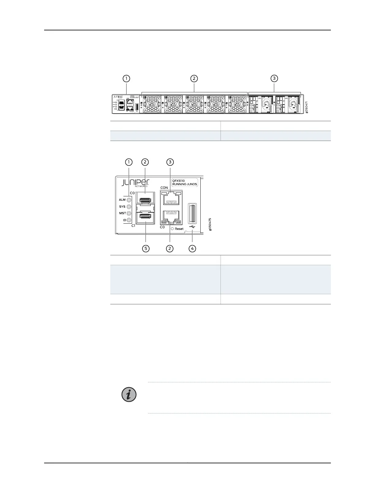
Figure 5: QFX5110 Switch, FRU End
3—1— Power supply unitsManagement panel
2—Fan modules
Figure 6: Management Panel Components on QFX5110
4—1— USB portStatus LEDs
5—2—
em1–SFP management Ethernet port (C1)
Cage (socket for either 1-GbE copper SFP
or fiber SFP)
em0–RJ-45 (1000BASE-T) management
Ethernet port (C0)
and an additional SFP management
Ethernet port (second C0)
3—
RJ-45 console port (CON)
The management panel consists of the following components:
•
Status LEDs, see “QFX5110 Chassis Status LEDs” on page 37.
•
Switch product number
•
Management ports C0 and C1, see “QFX5110 Management Port LEDs” on page 36.
•
C0–Use the RJ-45 connectors for 10/100/1000BASE-T or to cable a virtual
management Ethernet (VME) interface for spine members in a VCF. See “Connecting
a Device to a Network for Out-of-Band Management” on page 93.
NOTE: If both C0 ports are cabled, the copper C0 has priority over the
fiber C0.
•
C1–Use the SFP connector for 1000BASE-X.
35Copyright © 2019, Juniper Networks, Inc.
Chapter 1: Overview

 Loading...


