Fan Modules
The fan modules in QFX5110 devices are hot-insertable and hot-removable FRUs. These
fan modules are designed for one of the two available airflow directions (Airflow In or
Airflow Out). The fan modules are also color-coded for the airflow direction. The fan
modules are installed in the fan module slots between the management panel and the
power supplies.
The QFX5110 fan modules have five fan modules numbered 0 through 4 counting from
left to right. Each fan module slot has a fan icon next to it.
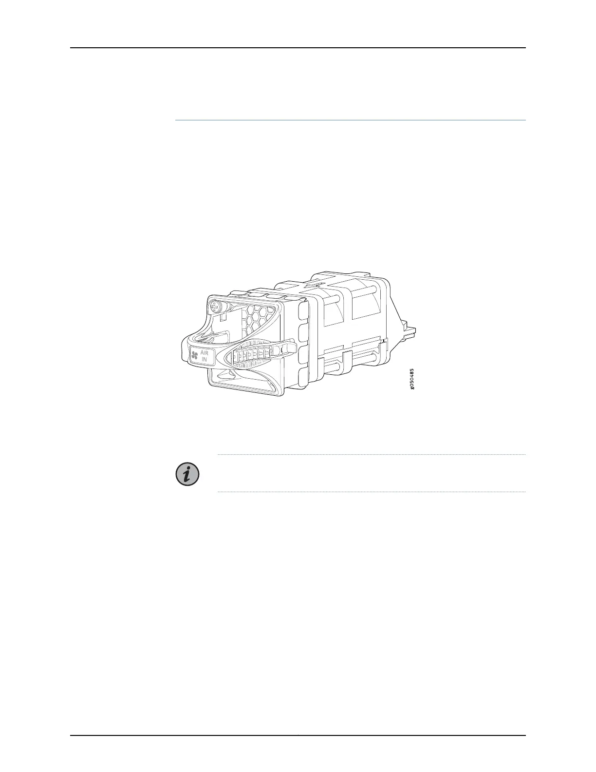
Figure 9 on page 40 shows the fan module.
Figure 9: QFX5110 Fan Module
You remove and replace a fan module from the FRU end of the chassis. The switch
continues to operate for a limited period of time (30 seconds) during the replacement
of the fan module without thermal shutdown.
NOTE: All fan modules must be installed for optimal operation of the switch.
The fan modules are available in two product SKUs that have different airflow directions,
airflow in and airflow out. Airflow in is indicated on the module by the azure blue color
and a label marked AIR IN. Airflow in this version of the fan module bring air into the fans
and power supplies and exhaust air through the ports. Likewise, airflow out is indicated
by a gold color and a label marked AIR OUT. Airflow out versions of the fan module brings
air into the switch through the vents around the ports and exhaust air through the fans
and power supplies. Table 11 on page 41 lists the available fan module product SKUs and
the direction of airflow in them.
Copyright © 2019, Juniper Networks, Inc.40
QFX5110 Switch Hardware Guide
 Loading...


