EasyManuals Logo

Juniper QFX Series Hardware Guide

Juniper QFX Series
176 pages
To Next Page IconTo Next Page
To Previous Page IconTo Previous Page
Page #81 background imageLoading...
Page #81 background image
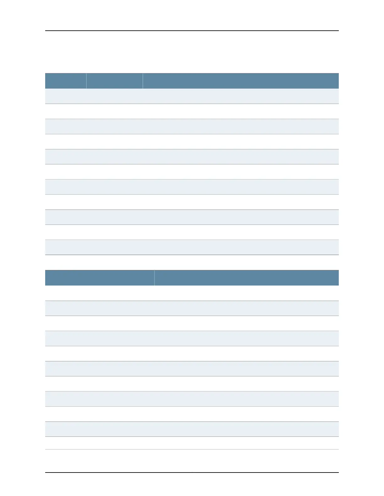
Table 36: SFP+ Network Port Connector Pinout Information (continued)
DescriptionSignalPin
Module receiver groundVeeR10
Module receiver groundVeeR11
Receiver inverted data outputRD-12
Receiver noninverted data outputRD+13
Module receiver groundVeeR14
Module receiver 3.3 V supplyVccR15
Module transmitter 3.3 V supplyVccT16
Module transmitter groundVeeT17
Transmitter noninverted data inputTD+18
Transmitter inverted data inputTD-19
Module transmitter groundVeeT20
Table 37: QSFP+ and QSFP28 Network Port Connector Pinout Information
SignalPin
GND1
TX2n2
TX2p3
GND4
TX4n5
TX4p6
GND7
ModSelL8
LPMode_Reset9
VccRx10
SCL11
81Copyright © 2019, Juniper Networks, Inc.
Chapter 2: Site Planning, Preparation, and Specifications

Table of Contents

Other manuals for Juniper QFX Series

Questions and Answers:

Question and Answer IconNeed help?

Do you have a question about the Juniper QFX Series and is the answer not in the manual?

Juniper QFX Series Specifications

General IconGeneral
CategorySwitch
SeriesQFX
Form Factor1U, 2U, and modular chassis options
Power SupplyRedundant, hot-swappable power supplies
Coolinghot-swappable fans
Virtual ChassisSupported on certain models
Typical UseData center, cloud
Operating SystemJunos OS
ManagementCLI
Key FeaturesHigh performance, low latency, automation
LatencySub-microsecond latency
Port DensityVaries by model (e.g., QFX5100: up to 48x10GbE + 6x40GbE)

Related product manuals