•
The grounding cable that you provide for a QFX5110 must be 14 AWG (2 mm²), minimum
60° C wire, or as permitted by the local code.
See Also QFX5110 Power System on page 45•
• Maintaining QFX5110 Power Supplies on page 110
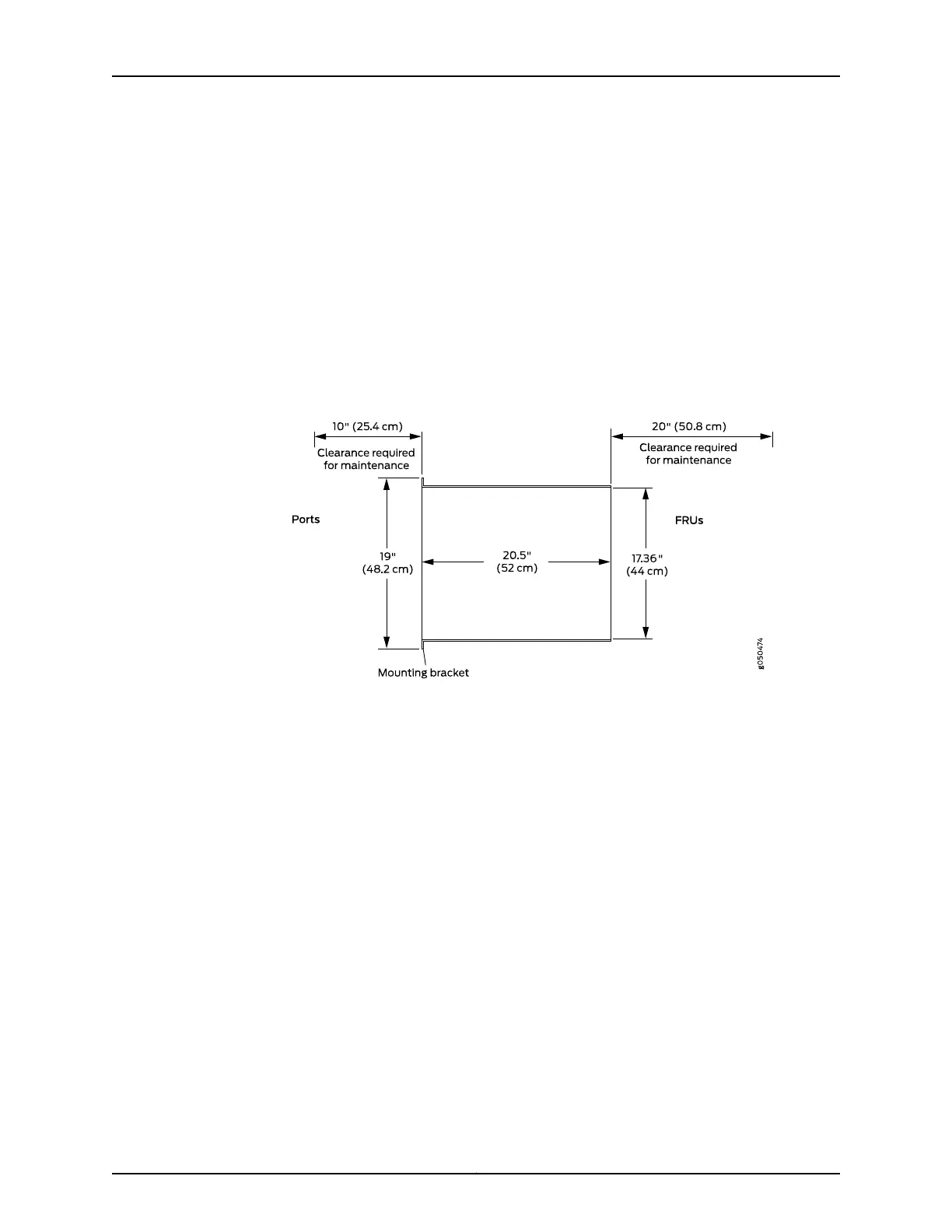
QFX5110 Clearance Requirements for Airflow and Hardware Maintenance
When planning the site for installing a QFX5110, you must allow sufficient clearance
around the installed chassis (see Figure 21 on page 60).
Figure 21: Clearance Requirements for Airflow and Hardware Maintenance for a QFX5110
•
For the cooling system to function properly, the airflow around the chassis must be
unrestricted. See “QFX5110 Cooling System and Airflow Description” on page 39 for
more information about the airflow through the chassis.
•
If you are mounting a QFX5110 in a rack with other equipment, ensure that the exhaust
from other equipment does not blow into the intake vents of the chassis.
•
Leave at least 24 in. (61 cm) both in front of and behind the QFX5110. For service
personnel to remove and install hardware components, you must leave adequate
space at the front and back of the switch. NEBS GR-63 recommends that you allow
at least 30 in. (76.2 cm) in front of the rack or cabinet and 24 in. (61 cm) behind the
rack or cabinet.
QFX5110 Chassis Physical Specifications
The QFX5110 models are rigid sheet-metal structures that houses the hardware
components.Table 23 on page 61 summarizesthe physical specificationsof the QFX5110.
Copyright © 2019, Juniper Networks, Inc.60
QFX5110 Switch Hardware Guide

 Loading...


