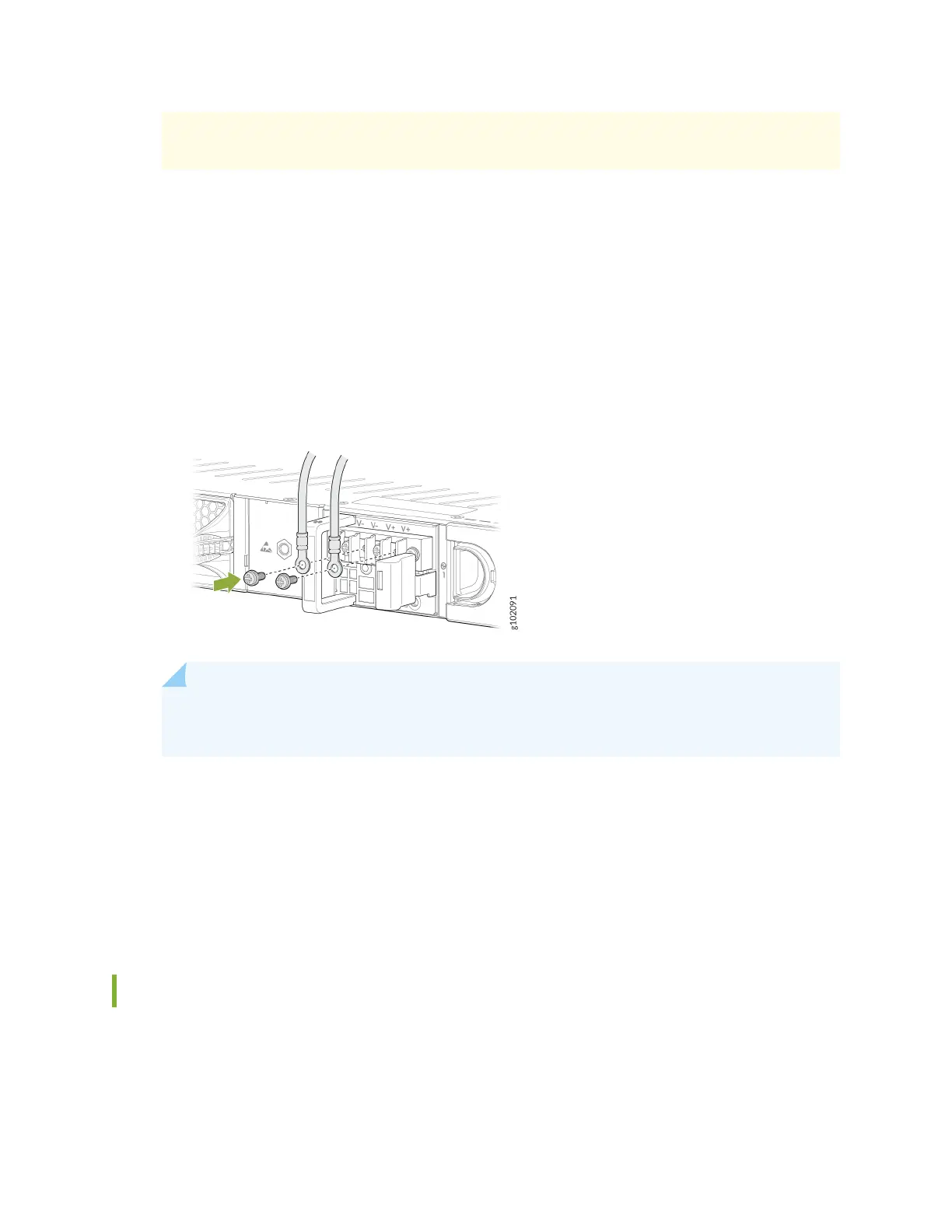
the external DC power source at your site determines the color coding for the leads
on the power cables that aach to the terminal studs on each power supply.
5. Remove the screws and square washers from the terminals, using a Phillips (+) screwdriver, number
2.
6. Secure each power cable ring terminal to the terminals with the square washers and the screws.
Apply between 23 in.-lb (2.6 Nm) and 25 in.-lb (2.8 Nm) of torque to each screw.
• Secure each posive (+) DC source power cable ring terminal to an RTN terminal.
• Secure each negave (–) DC source power cable ring terminal to a -48V (input) terminal.
Figure 36: Connecng the DC Power Cables
NOTE: Connect each power cable to a dedicated external circuit breaker. We recommend
that you use a 10 A (80 VDC), or as permied by the local code.
7. Replace the clear plasc cover over the terminal studs on the faceplate.
8. Verify that the power cables are connected correctly. The cables must not touch or block access to
rewall components, and they must not cause a tripping hazard.
9. Switch the circuit breaker on the panel board that services the DC circuit to the ON (|) posion.
10. Connect the power cables to the external DC power source. If the external DC power source has a
switch, set it to the ON (|) posion.
Power O the SRX1600
You can power o the rewall in any of the following two ways:
• Graceful shutdown—Press and immediately release the Power buon. The device begins gracefully
shung down the operang system (OS) and then powers itself o.
61