3-6 Keysight B1505A User’s Guide, Edition 12
Accessories
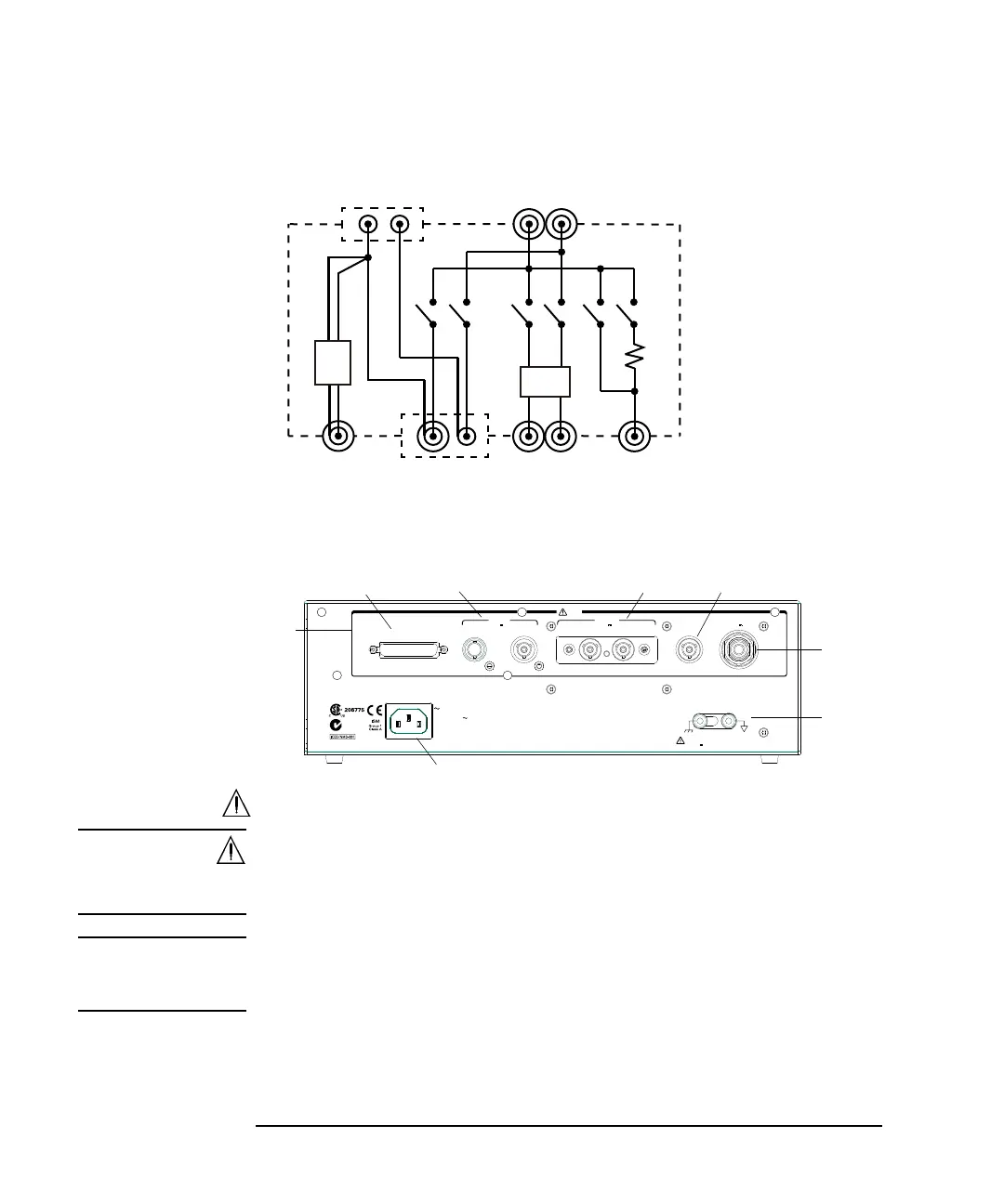
Figure 3-2 Module Selector Simplified Internal Connections
Rear Panel
1. Input
WARNING The connector cap must be connected to the unused input connectors for safety.
Le capuchon du connecteur doit être raccordé aux connecteurs d'entrée
inutilisés.
NOTE Do not put any conductor on the HCSMU Low Force and Low Sense terminals,
outer conductor of the coaxial connectors. Putting conductor of circuit common,
chassis ground, or any potential on causes the measurement error.
Low High
SF
S: Sense
F: Force
P.A
P.A
GNDU HCSMU HPSMU HVSMU
SF
SF
SF
F
P.A:
Protection adapter
SF
GNDU force and sense
are connected to Low
sense line.
HVSMU force is connected
to High sense line.
100 kW
GNDU
HPSMU
±200 V Max
HCSMU
±40 V Max
Digital I/O
SenseForce SenseForce
N10149
HVSMU
LINE
100–240 V
50/60 Hz
65 VA Max
Circuit
Common
For floating measurements disconnect
shorting bar. Do not apply more than
±42 V
to Circuit Common.
Input
±3 kV Max
2
3
a
b
c
d
e
1