Keysight B1505A User’s Guide, Edition 12 3-5
Accessories
Then use high current and high voltage cable with HV(plug) connector for
Force, high voltage cable with HV(plug) connector for Sense, manipulators,
and such.
Guard must be opened but should be extended as close as possible to the
device terminal for reducing the leakage current of the extension cable.
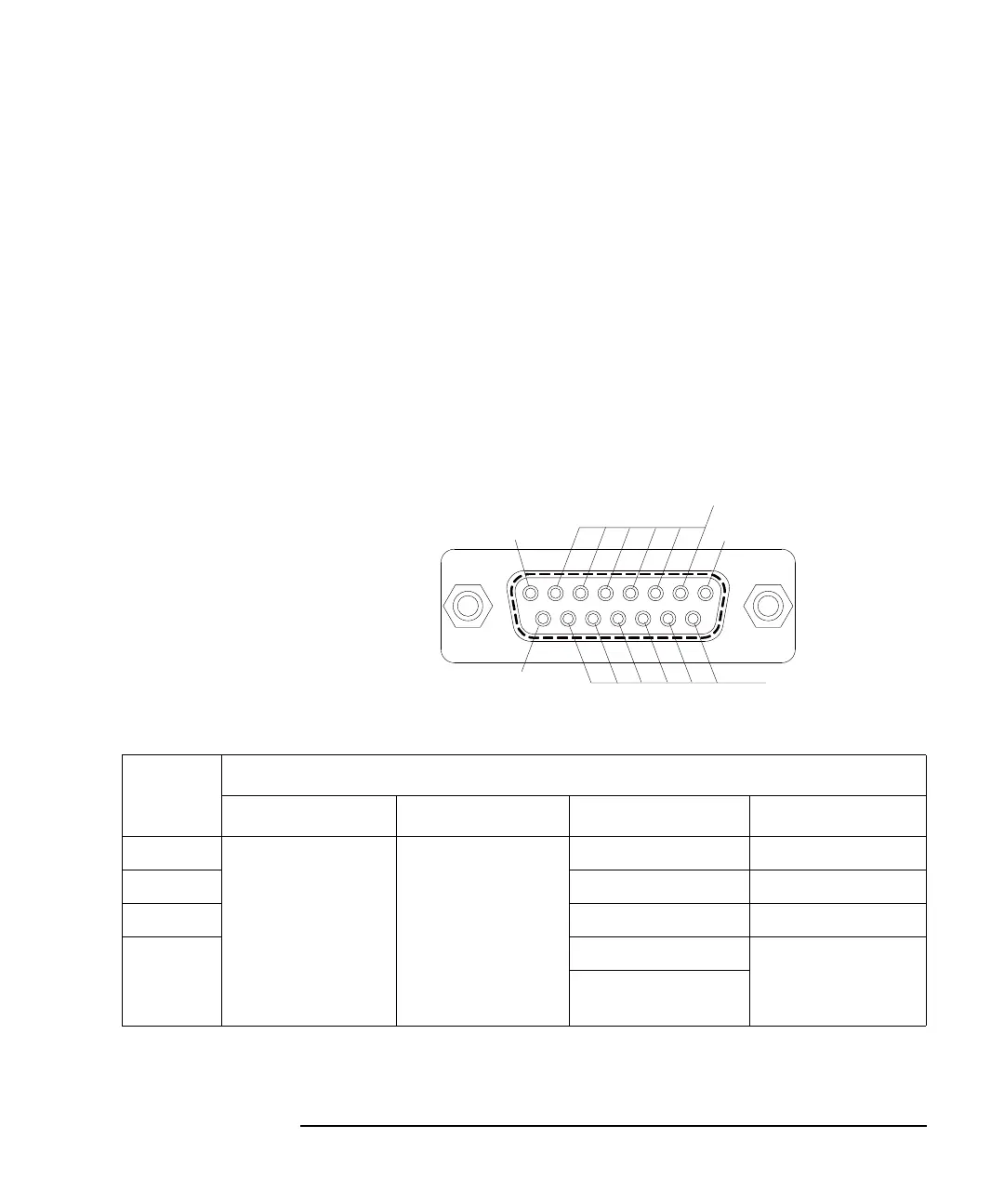
c. External Relay Control Output connector
D-sub 15 pin connector. See Figure 3-1 for pin assignment. Relay control 1
to 6 are used to control an external relay and controlled by using the FLEX
command. See Keysight B1500 Programming Guide for the FLEX
command.
Relay control signal level: 0 V or 12 V, normally 0 V (circuit common)
Figure 3-1 External Relay Control Output Connector
Table 3-1 N1258A Status Indicator and Connection Path
Status
indicator
N1258A output connectors
Low Sense Low Force High Sense High Force
Open HCSMU Low Sense
+ GNDU Force
+ GNDU Sense
HCSMU Low Force Open Open
HPSMU HPSMU Sense HPSMU Force
HCSMU HCSMU High Sense HCSMU High Force
HVSMU HVSMU Force
Open
HVSMU Force
+ Series resistor
12 V
Circut common (0 V)
Circut common (0 V)
Circut common (0 V)
Relay control
1
6
5
4
3
2