3-50 Keysight B1505A User’s Guide, Edition 12
Accessories
• N1265-61752: short wire (black), 2 ea.
For making the Kelvin connection, Force and Sense must be connected
together at the device terminal.
Figure 3-16 and Figure 3-17 show connection examples.
3. Set the current control device on the left socket or connect the load resistor
between the studs for the resistor.
The current control device must be an extra 3-pin inline package device
which is expected to have the same characteristics as DUT. If the device is
not available, use a load resistor. The resistor must satisfy the following
specifications.
Resistance = Vr/Ir (Vr: rated voltage, Ir: rated current)
Peak power Vr Ir 1 ms
4. Set your DUT on the right socket.
5. Close the fixture cover and perform measurement.
CAUTION Do not apply voltage/current over the maximum limit of the socket module.
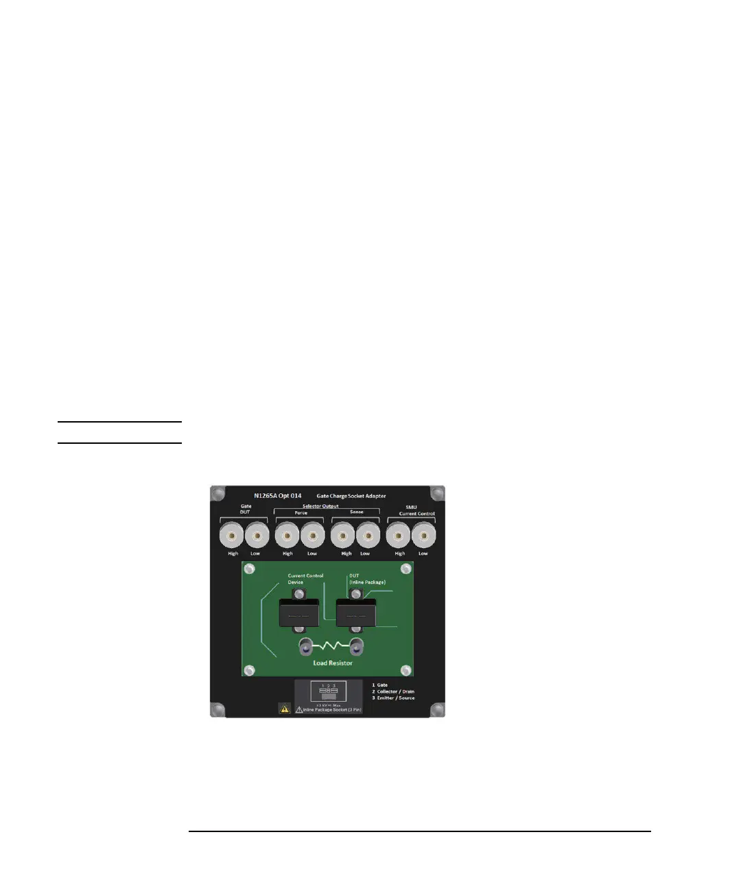
Figure 3-15 Gate Charge Socket Module
Collector / Drain
Emier / Source Base / Gate
N1259A Opt 013
Force Sense
Force Sense
Force Sense
Curve Tracer Test Adapter Socket
1
2
5
6
4
3
Gate DUT
High: Max. 30 V / 1 A
Low: Max. 10 V / 1 A
Selector Out Force
High: Max. 3000 V / 500 A
Low: Max. 10 V / 500 A
Selector Out Sense
High: Max. 3000 V /20 mA
Low: Max. 10 V / 20 mA
SMU Current Control
High: Max. 30 V / 1A floating 3000 V
Low: Max. 10 V / 1A floating 3000 V
A
BC